
Intermediate · visual course

Embedded Systems

An embedded system combines dedicated software and hardware under real limits for time, memory, energy and safety.

CC++Microcontrollers 4 guided sessions 8 skill tracks 3 example projects
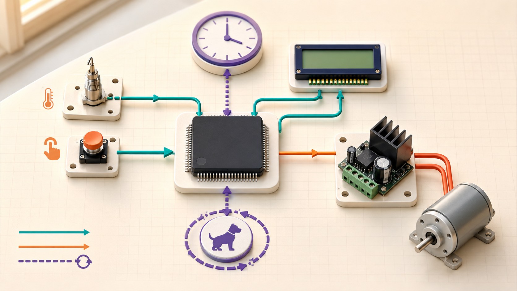
Three-dimensional embedded system connecting sensors, timer, microcontroller, display and motor driver
Concept overview · generated for this Academy4Tech lesson
Start here

See the system, then build it.

Reliable embedded code responds to events, protects shared data and always has a defined safe state.

01Describe microcontroller memory, peripherals and firmware
02Choose GPIO, ADC, UART, I2C or SPI for a connection
03Explain polling, interrupts and timers
04Design a state machine with timeout and fault recovery
Your progress Keep your learning momentum going

0 of 4 sessions complete

Interactive 3D learning studio

Firmware timing studio

Connect hardware inputs, deterministic timing, state and safe outputs inside a microcontroller.

Interactive system model · loads on request Poster mode
Explore the system in 3D Inspect the labelled subsystems and watch their modelled process. The lesson flow beside it is a separate conceptual sequence unless it explicitly names the same subsystem. The poster remains available if WebGL is unsupported.
Selected lesson · conceptual flow

Hardware meets firmware

What makes a system embedded?

Step 1 of 4 · Reset

Step through this lesson’s conceptual sequence here. Inspect the separate 3D subsystem model below it to understand the system’s structure.

3D subsystem inspector · 4 model parts
Mini experiment

Change one variable. Predict first, then test.

Set a 10–30 ms control period.

20 ms
Live result Move the control to test your prediction

Set a 10–30 ms control period.

Every highlighted 3D group corresponds to a labelled system part. A slider changes the model only when that relationship can be represented faithfully; otherwise the geometry stays still and the live calculation explains the effect. The model simplifies scale and geometry, so use the lesson’s safety notes, measurements and official documentation when building a real system.

01
Session 1 · 20 min

Hardware meets firmware

What makes a system embedded?

Understand it

An embedded system is built into a product to perform focused functions. A microcontroller combines processor, memory and peripherals. Firmware starts at reset, initializes hardware and then handles events or repeats a control loop within limited resources.

Interactive concept flow

Step 1 of 4 Reset

Choose a step to inspect it, or run the complete sequence.

Sequence progress
1 / 4
Picture it

A useful analogy

A washing-machine controller has one dedicated workplace, unlike a laptop that runs many unrelated applications.

Apply it

Worked example

A thermostat reads temperature, applies a control rule, drives a relay safely and updates a small display.

Try it
  1. Choose one appliance.
  2. List its inputs, outputs and timing needs.
  3. Identify its safe state after a fault.
Quick checkWhat is firmware?

Answer: Software stored for and closely controlling an embedded device.

02
Session 2 · 25 min

Pins and communication buses

How do components exchange data?

Understand it

GPIO handles simple digital states; ADC measures analog voltage. UART is an asynchronous serial link, I2C connects addressed devices on shared data and clock lines, and SPI uses separate clock and data paths for fast controller-peripheral exchange.

Interactive concept flow

Step 1 of 4 Peripheral need

Choose a step to inspect it, or run the complete sequence.

Sequence progress
1 / 4
Picture it

A useful analogy

Different roads suit a single driveway, a shared bus route or a fast dedicated delivery lane.

Apply it

Worked example

Use I2C for several low-speed addressed sensors and SPI for a display that needs faster transfers.

Try it
  1. Match four peripherals to interfaces.
  2. Count required signal wires.
  3. Check voltage compatibility and shared ground.
Quick checkWhat allows several I2C devices to share a bus?

Answer: Each compatible device uses an address on the shared clock and data lines.

03
Session 3 · 25 min

Time, polling and interrupts

How can a controller respond at the right moment?

Understand it

Polling repeatedly checks for change. An interrupt pauses normal flow to handle an event quickly, then returns. Hardware timers schedule precise events. Interrupt handlers should be short; lengthy work can be signalled for the main loop.

Interactive concept flow

Step 1 of 4 Normal task

Choose a step to inspect it, or run the complete sequence.

Sequence progress
1 / 4
Picture it

A useful analogy

Polling is repeatedly checking the door; an interrupt is a doorbell; a timer is an alarm clock.

Apply it

Worked example

A timer triggers sensor sampling every 10 ms while a button interrupt records an emergency request for the main loop.

Try it
  1. Classify three events as polling, interrupt or timer.
  2. Draw a timing line.
  3. Mark work that should stay outside an interrupt handler.
Quick checkWhy keep an interrupt handler short?

Answer: Long handlers delay other time-critical work and can make system timing unpredictable.

04
Session 4 · 30 min

State machines and fault recovery

How can behaviour stay clear as a product grows?

Understand it

A finite-state machine lists valid states, events and transitions. Outputs depend on the current state. Timeouts prevent indefinite waiting, a watchdog can reset stalled software, and fault states put hardware into a safe condition while preserving useful diagnostic information.

Interactive concept flow

Step 1 of 4 State

Choose a step to inspect it, or run the complete sequence.

Sequence progress
1 / 4
Picture it

A useful analogy

A lift has states such as doors open, doors closing and moving; only certain transitions are safe.

Apply it

Worked example

A motor controller moves from IDLE to RUN only after a start event, enters FAULT on overcurrent, and returns only after power is safe and a reset is requested.

Try it
  1. Draw states for an automatic fan.
  2. Add sensor failure and over-temperature events.
  3. Define the output in every state.
Quick checkWhat is a safe state?

Answer: A defined condition that reduces risk when the system cannot continue normal operation.

Beyond the guided sessions

Explore the whole Embedded Systems field

The guided sessions teach the foundations. This map widens the view across 8 important tracks, with explanations, practice prompts, knowledge checks, and official sources for deeper study.

Connect microcontroller hardware and deterministic firmware, then verify timing, reliability, security, updates, and safe behavior across the device lifecycle.

Field map 0 of 8 tracks explored
Open a track to add it to your journey.
  1. Foundation Microcontroller architecture and toolchains
    Track overview

    Embedded software runs against a specific processor, memory map, peripheral set, boot path, and build toolchain, all under tight resource limits.

    Core concepts

    Four ideas to understand

    1. CPU, registers, and memory map

      The processor executes instructions and accesses RAM, flash, peripherals, and control registers through addresses. Volatile memory loses state, while nonvolatile memory retains code and settings.

    2. Reset and boot sequence

      After reset, startup code establishes stack, memory initialization, clocks, and runtime state before main executes. A bootloader may verify or select an application image first.

    3. Cross-compilation and linking

      A host compiler generates code for the target architecture, and a linker places sections into the target memory map. The map file reveals flash and RAM use that source code can hide.

    4. Debug and trace interfaces

      SWD or JTAG can program memory, halt the core, inspect state, and set breakpoints; trace adds time-sensitive execution evidence. Debug access must be controlled on deployed products.

    Check your thinking What does the linker map tell you that a successful compile does not?
    Answer

    It shows where program sections and symbols were placed and how much target flash and RAM they consume.

  2. Foundation C firmware, state, and hardware abstraction
    Track overview

    Clear ownership of state, types, memory, and hardware boundaries makes low-level firmware understandable and reduces defects that compile successfully.

    Core concepts

    Four ideas to understand

    1. Types, memory safety, and bit operations

      Register fields and protocols need explicit widths, masks, shifts, signedness, and byte order. Bounds, pointer lifetimes, stack use, signed overflow, undefined shifts, and implicit conversions must be checked because memory errors can corrupt unrelated state.

    2. volatile and shared state

      volatile tells the compiler that an access may change outside normal code flow, as with a hardware register. It does not make multi-step operations atomic or synchronize threads.

    3. State machines

      A state machine defines allowed states, events, guards, actions, and transitions. Explicit invalid-event behavior prevents a device from drifting into undocumented modes.

    4. Drivers and abstraction boundaries

      A driver translates device details into a narrow interface with documented timing and error behavior. Higher layers should depend on that contract rather than raw registers.

    Check your thinking Does volatile make an increment shared with an interrupt safe?
    Answer

    No; it forces accesses but does not make the read-modify-write sequence atomic or prevent races.

  3. Applied GPIO, timers, ADCs, and serial buses
    Track overview

    Peripherals connect software to electrical reality, so pin configuration, voltage compatibility, bus timing, and error signals belong in the same design.

    Core concepts

    Four ideas to understand

    1. GPIO electrical behavior

      A pin can be input, push-pull output, open-drain, analog, or alternate function, with finite voltage and current limits. Pull resistors establish a known state when no device drives the line.

    2. Timers and PWM

      A timer counts clock ticks and can capture events, schedule compares, or generate PWM without constant CPU work. Prescaler and period choices trade resolution against range.

    3. ADC acquisition

      An ADC samples a bounded analog range into discrete codes. Source impedance, reference quality, acquisition time, resolution, and noise determine useful accuracy.

    4. UART, SPI, and I2C

      UART is asynchronous framed serial and is commonly used point-to-point; SPI is clocked and can transfer in both directions using chip selects; I2C shares addressed open-drain lines. Each needs electrical limits, timing, framing, and timeout handling.

    Check your thinking Why do I2C signal lines normally need pull-up resistors?
    Answer

    Devices generally pull the open-drain lines low but do not drive them high, so resistors restore the HIGH level.

  4. Applied Interrupts, concurrency, and timing
    Track overview

    Asynchronous events make firmware responsive but introduce latency, races, priority interactions, and deadlines that ordinary sequential reasoning misses.

    Core concepts

    Four ideas to understand

    1. Interrupt service routines

      An ISR should acknowledge the source, capture minimal data, and defer lengthy work. Blocking, allocation, or slow I/O in an ISR increases system latency and failure risk.

    2. Atomicity and critical sections

      A shared operation is safe only if it cannot be interrupted in an inconsistent state or is protected by an appropriate primitive. Keep interrupt-disabled regions short and bounded.

    3. Latency, jitter, and deadlines

      Latency is delay before work begins, jitter is its variation, and a deadline is the latest useful completion time. Measure worst observed timing under load rather than relying on an average.

    4. Queues and event handoff

      Queues or event objects transfer work from producers such as ISRs to consumers while defining buffering and overflow behavior. Every full-queue policy must be intentional.

    Check your thinking Why should a lengthy calculation be deferred out of an ISR?
    Answer

    It delays other interrupts and scheduled work, increasing latency and the chance of missed deadlines or data.

  5. Advanced RTOS scheduling and communication
    Track overview

    An RTOS provides schedulable threads and synchronization, but developers still must design priorities, ownership, timeouts, and bounded resource use.

    Core concepts

    Four ideas to understand

    1. Threads and priorities

      Threads divide concurrent responsibilities and the scheduler chooses which ready thread runs. Priority should follow timing need, not perceived feature importance.

    2. Mutexes, semaphores, and events

      Mutexes protect ownership, semaphores count or signal availability, and events communicate conditions. Using the wrong primitive can hide lost signals or allow concurrent access.

    3. Priority inversion and deadlock

      A low-priority owner can delay a high-priority task, while circular lock dependencies can stop all progress. Consistent lock order, short ownership, and suitable RTOS protocols reduce these risks.

    4. Stack and memory sizing

      Each thread needs enough stack for its deepest call path and interrupts, but excess wastes scarce RAM. Use runtime high-water evidence and guard mechanisms across worst-case tests.

    Check your thinking What is priority inversion?
    Answer

    A higher-priority thread is indirectly delayed because a lower-priority thread owns a resource it needs.

  6. Applied Power, reset, storage, and field reliability
    Track overview

    Real devices face supply ramps, brownouts, noisy environments, finite write endurance, and unexpected resets; robust firmware treats them as normal design inputs.

    Core concepts

    Four ideas to understand

    1. Sleep states and energy budgeting

      Energy depends on active current, sleep current, and time in each state. Wake sources and peripheral leakage often decide whether a low-power estimate is realistic.

    2. Watchdogs and reset causes

      A watchdog recovers only when healthy software refreshes it through a controlled path. Store and report reset cause so repeated resets become diagnosable evidence.

    3. Brownout and startup ordering

      A brownout detector holds or resets logic when supply voltage cannot guarantee operation. Outputs should enter safe states before clocks, peripherals, and dependent rails become valid.

    4. Nonvolatile data integrity

      Configuration writes need versioning, range checks, integrity codes, wear management, and power-loss-safe commit. Keep a recoverable default when stored data is invalid.

    Check your thinking Why should a watchdog not be refreshed unconditionally from a timer interrupt?
    Answer

    The interrupt may continue even when application work is stuck, masking the failure the watchdog is meant to detect.

  7. Advanced Debugging, testing, and observability
    Track overview

    Repeatable builds, layered tests, timing-aware diagnostics, and fault injection turn intermittent firmware behavior into evidence that can be reproduced and fixed.

    Core concepts

    Four ideas to understand

    1. Unit and integration tests

      Unit tests isolate logic with controlled dependencies; integration tests exercise real drivers, scheduling, and hardware boundaries. Both need deterministic setup and clear pass criteria.

    2. Hardware-in-the-loop testing

      HIL equipment stimulates real I/O and observes outputs while controlling the environment. It reveals electrical and timing effects that host-only tests cannot represent.

    3. Logging, assertions, and crash data

      Diagnostics should capture state, timestamps, build identity, and reset information without breaking deadlines. Assertions detect violated assumptions but deployed behavior must still fail safely.

    4. Fault and boundary injection

      Disconnects, corrupt frames, exhausted memory, full queues, slow devices, and wraparound expose hidden assumptions. Inject faults safely and verify both detection and recovery.

    Check your thinking What important gap does hardware-in-the-loop testing fill?
    Answer

    It tests real target timing and electrical I/O while the surrounding conditions remain controlled and repeatable.

  8. Advanced Secure updates and safe lifecycle
    Track overview

    Connected firmware must protect identity, configuration, data, commands, and update paths while preserving recovery and the device's physical safety function.

    Core concepts

    Four ideas to understand

    1. Device identity and least privilege

      Each device needs a manageable identity and interfaces should expose only necessary operations. Debug ports, service accounts, and default credentials are part of the attack surface.

    2. Secure boot and signed updates

      A chain of trust verifies authorized code before execution, and signed updates prove origin and integrity. Anti-rollback policy must balance known-vulnerability prevention with recovery needs.

    3. Protected data and configuration

      Protect sensitive data at rest and in transit, validate configuration changes, and log security-relevant events. Secret storage and key rotation need a lifecycle plan.

    4. Safe update and end-of-life behavior

      Power loss or a bad image must not brick the device or activate unsafe outputs. Define rollback, recovery, vulnerability response, support period, and secure decommissioning.

    Check your thinking What does a signed firmware image prove, and what does it not prove?
    Answer

    It can prove authorized origin and integrity; it does not prove that the authorized firmware is bug-free or physically safe.

Verified next steps

Official references

Use these primary sources to extend the explanations and check current guidance.

  1. Arm Cortex-M resources
  2. Zephyr Project Getting Started Guide
  3. Zephyr Project Kernel Services
  4. Zephyr Project Test Framework
  5. National Institute of Standards and Technology IoT Device Cybersecurity Capability Core Baseline
  6. Zephyr Project Device Firmware Upgrade with MCUboot
  7. National Institute of Standards and Technology NIST IR 8259 Rev. 1 — Foundational Cybersecurity Activities for IoT Product Manufacturers
Three-project build pathway

Learn Embedded Systems by making it work.

Start small, combine the ideas, then complete a measured challenge. Every project includes a material list, four build milestones, evidence to collect, and a safe next step.

  1. Starter · 3–5 hours Program a non-blocking status controller Learn one dependable building block Implement a button-controlled LED state machine whose timer-driven behavior, debouncing, build configuration, and timing can be explained and tested without hidden delays.
    What you will learn

    Learning goals

    • Relate GPIO registers, board configuration, compiler output, and firmware behavior.
    • Model input handling and output patterns as explicit states and events.
    • Measure timing and responsiveness rather than assuming a delay loop is accurate.
    Prepare

    Materials and tools

    • A supported low-voltage microcontroller development board or vendor simulator
    • C toolchain, debugger, serial console, and board documentation
    • On-board button and LED, or equivalent low-voltage inputs and current-limited outputs
    Build sequence

    Four milestones

    1. Draw the finite-state machine for off, steady, slow-blink, and fast-blink states with button and timer events.

    2. Create a reproducible build, initialize GPIO and a hardware timer, and verify the pin polarity against the schematic.

    3. Implement non-blocking debouncing and state transitions, then add timestamped serial diagnostics outside timing-critical paths.

    4. Test short press, long press, contact bounce, rapid presses, timer wraparound, and reset; compare measured blink periods with requirements.

    Prove it works

    Evidence to collect

    • The code contains no busy-wait delay in the main control path, and the state diagram maps directly to named implementation states.
    • A timing trace shows each blink rate and worst-case button response meet declared tolerances.
    • A clean rebuild plus test table reproduces every transition, bounce case, reset state, and wraparound result.
  2. Builder · 6–9 hours Build a deadline-aware telemetry node Connect multiple ideas into a working system Create firmware that samples a low-voltage or simulated sensor, timestamps and queues readings, reports telemetry over UART, and remains responsive under controlled load and communication faults.
    What you will learn

    Learning goals

    • Assign periodic work, interrupts, queues, and tasks according to latency and ownership.
    • Measure execution time, jitter, queue occupancy, memory use, and missed deadlines.
    • Design bounded behavior for stale data, buffer pressure, bus errors, and watchdog recovery.
    Prepare

    Materials and tools

    • A Zephyr-supported development board or simulator
    • A low-voltage I²C sensor or deterministic mock driver
    • Logic analyzer or GPIO timing pin if available, serial terminal, debugger, and Zephyr test tools
    Build sequence

    Four milestones

    1. Write timing, freshness, throughput, memory, and fault requirements; draw ownership and data flow from interrupt to report.

    2. Implement periodic acquisition and timestamped queue transfer with a mock driver first, keeping interrupt work short and bounded.

    3. Add telemetry framing, counters, stale-data status, bus-error handling, queue-overflow policy, and a correctly serviced watchdog.

    4. Run normal, burst-load, delayed-consumer, sensor-error, and reset tests; produce timing histograms and resource measurements.

    Prove it works

    Evidence to collect

    • Worst-case measured acquisition jitter, reporting latency, queue depth, stack margin, and CPU load satisfy stated limits.
    • Injected bus, backlog, malformed-frame, and task-stall cases produce deterministic counters and bounded recovery without silent data corruption.
    • Automated tests cover frame encoding, state transitions, timeout arithmetic, and at least one hardware-independent driver boundary.
  3. Challenge · 10–14 hours Prove a resilient signed-update workflow Test, measure, and improve a complete solution Build a controlled emulator or spare-board lab for signed firmware updates, version identity, confirmation, rollback, recovery, logging, and lifecycle documentation.
    What you will learn

    Learning goals

    • Map device identity, authorization, software update, data protection, and cybersecurity-state reporting into product requirements.
    • Separate bootloader trust, image validation, application health confirmation, and rollback responsibilities.
    • Test interrupted, invalid, incompatible, and vulnerable update paths without endangering production devices.
    Prepare

    Materials and tools

    • Zephyr and MCUboot in a supported emulator or an expendable development board with documented recovery
    • Local development signing keys created only for this lab
    • Debugger or recovery programmer, serial logs, version-control repository, and an automated test harness
    Build sequence

    Four milestones

    1. Write a threat model and lifecycle policy covering identity, signing-key handling, versioning, authorization, support period, logs, rollback, and recovery.

    2. Build baseline and candidate images, sign the candidate with a lab key, request a test boot, and confirm it only after a defined health check.

    3. Exercise invalid signature, corrupted image, incompatible version, failed health check, and controlled interruption using emulator fault controls or documented board recovery.

    4. Automate the update matrix and publish retained evidence: hashes, versions, signatures, boot decisions, recovery result, known limitations, and key-destruction procedure.

    Prove it works

    Evidence to collect

    • Valid authorized images boot and confirm only after health criteria, while invalid, corrupted, and unauthorized images are rejected with attributable logs.
    • Every supported interruption point ends in a documented bootable baseline, retry, or explicit recovery path without relying on an undocumented manual trick.
    • A traceable report links lifecycle requirements to tests, artifacts, exact tool versions, and unresolved residual risks.
Words to know

Build your vocabulary.

Firmware
Software closely tied to an embedded device.
Peripheral
Hardware controlled by or connected to the processor.
Interrupt
An event that temporarily redirects processor execution.
Timer
Hardware that measures or schedules time intervals.
State machine
Behaviour model built from states and allowed transitions.
Watchdog
A mechanism that detects stalled software and initiates recovery.
Work safely

Before you power or move anything.

  • Use low-voltage loads or simulated outputs while learning.
  • Separate motor power through a suitable driver.
  • Choose a safe output state before enabling hardware.
  • Treat watchdog reset as recovery, not a substitute for fixing faults.
Keep studying

Official documentation.

These lessons simplify the first ideas. Use the original documentation when building, checking details or moving to the next level.

Continue learning

Related Academy4Tech content.

Learn by building.

Choose a real project, identify the smallest subsystem you can test, and document what the measurement tells you.