
Beginner · visual course

Arduino

Arduino makes microcontroller experiments approachable by joining a programmable board, a simple code structure and reusable libraries.

Arduino IDEC++Sensors 4 guided sessions 8 skill tracks 3 example projects
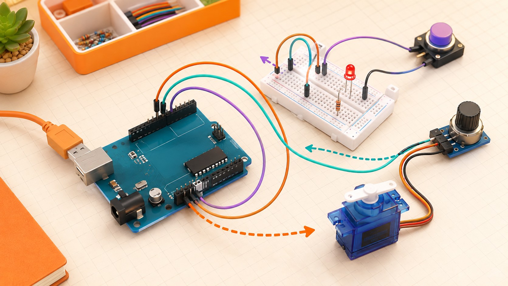
Three-dimensional microcontroller prototype with button, potentiometer, LED, resistor and servo
Concept overview · generated for this Academy4Tech lesson
Start here

See the system, then build it.

Build one input and one output first. Confirm each part works before combining them.

01Explain the setup-and-loop structure of a sketch
02Wire and control a digital input and output safely
03Read an analog signal and create PWM output
04Separate logic power from higher-current actuator power
Your progress Keep your learning momentum going

0 of 4 sessions complete

Interactive 3D learning studio

Arduino prototyping studio

Explore the path from an input pin through a sketch to a pulse-width-modulated output.

Interactive system model · loads on request Poster mode
Explore the system in 3D Inspect the labelled subsystems and watch their modelled process. The lesson flow beside it is a separate conceptual sequence unless it explicitly names the same subsystem. The poster remains available if WebGL is unsupported.
Selected lesson · conceptual flow

Board, pins and sketches

What happens when an Arduino sketch runs?

Step 1 of 4 · Power or reset

Step through this lesson’s conceptual sequence here. Inspect the separate 3D subsystem model below it to understand the system’s structure.

3D subsystem inspector · 4 model parts
Mini experiment

Change one variable. Predict first, then test.

Set a clearly visible output from 35% to 70%.

45%
Live result Move the control to test your prediction

Set a clearly visible output from 35% to 70%.

Every highlighted 3D group corresponds to a labelled system part. A slider changes the model only when that relationship can be represented faithfully; otherwise the geometry stays still and the live calculation explains the effect. The model simplifies scale and geometry, so use the lesson’s safety notes, measurements and official documentation when building a real system.

01
Session 1 · 20 min

Board, pins and sketches

What happens when an Arduino sketch runs?

Understand it

A microcontroller runs one program repeatedly. setup() runs once after start or reset; loop() then repeats. Pins can be configured as inputs or outputs. The uploaded program continues without a full desktop operating system.

Interactive concept flow

Step 1 of 4 Power or reset

Choose a step to inspect it, or run the complete sequence.

Sequence progress
1 / 4
Picture it

A useful analogy

Opening a classroom happens once, but checking the room and doing tasks repeats throughout the day.

Apply it

Worked example

Configure an LED pin in setup(), then turn it on and off with delays in loop().

Example codeRead each line, predict, then run
const int ledPin = 9;

void setup() {
  pinMode(ledPin, OUTPUT);
}

void loop() {
  digitalWrite(ledPin, HIGH);
  delay(500);
  digitalWrite(ledPin, LOW);
  delay(500);
}
Try it
  1. Open the built-in Blink example.
  2. Point to setup and loop.
  3. Predict what changing the delay will do.
Quick checkHow many times does setup() normally run?

Answer: Once after power-up or reset.

02
Session 2 · 25 min

Digital input and output

How does a controller read a button and control an LED?

Understand it

Digital signals use two logical states, HIGH and LOW. Inputs must not float between states, so a pull-up or pull-down resistor gives the pin a known default. An LED needs a series resistor to limit current.

Interactive concept flow

Step 1 of 4 Button state

Choose a step to inspect it, or run the complete sequence.

Sequence progress
1 / 4
Picture it

A useful analogy

A door is treated as open or closed, even though the handle moves through many positions.

Apply it

Worked example

Use INPUT_PULLUP for a button: an unpressed button reads HIGH and a pressed button connected to ground reads LOW.

Try it
  1. Draw a button using the internal pull-up.
  2. Trace the current path when pressed.
  3. Write a truth table for button and LED states.
Quick checkWhy does an LED need a resistor?

Answer: The resistor limits current so the LED and controller pin are not damaged.

03
Session 3 · 25 min

Analog input and PWM

How can a digital controller work with changing signals?

Understand it

An analog-to-digital converter turns a voltage range into a number. PWM rapidly switches a digital output to control average energy. PWM can dim an LED or command some motor drivers, but it is not a true analog voltage.

Interactive concept flow

Step 1 of 4 Changing voltage

Choose a step to inspect it, or run the complete sequence.

Sequence progress
1 / 4
Picture it

A useful analogy

A fast light switch can make a lamp appear dimmer when it spends less time on during each cycle.

Apply it

Worked example

Map a potentiometer reading to a PWM duty value so turning the knob changes LED brightness.

Try it
  1. Sketch low, middle and high PWM waveforms.
  2. Mark the on-time in each.
  3. Predict relative LED brightness.
Quick checkWhat does 25% PWM duty mean?

Answer: The output is on for about one quarter of each repeating cycle.

04
Session 4 · 30 min

Sensors, actuators and safe power

Why should motors not be powered directly from a pin?

Understand it

Sensors usually use small currents, but motors and servos can demand much more than a microcontroller pin supplies. Use a driver or suitable external supply, share ground where the circuit requires it, and protect against voltage spikes from inductive loads.

Interactive concept flow

Step 1 of 4 Sensor

Choose a step to inspect it, or run the complete sequence.

Sequence progress
1 / 4
Picture it

A useful analogy

A small doorbell button can signal a powerful gate motor, but it should not carry the motor current itself.

Apply it

Worked example

A light sensor tells the controller it is dark; the controller signals a transistor driver that powers a lamp.

Try it
  1. Label logic and load current paths on a motor diagram.
  2. Circle the shared reference connection.
  3. Add a safe power-off step before rewiring.
Quick checkWhat is the driver’s job?

Answer: It lets a low-power control signal safely switch or regulate a higher-current load.

Beyond the guided sessions

Explore the whole Arduino field

The guided sessions teach the foundations. This map widens the view across 8 important tracks, with explanations, practice prompts, knowledge checks, and official sources for deeper study.

Move from safe board setup and basic circuits to timed sensing, motors, communication, and dependable embedded builds.

Field map 0 of 8 tracks explored
Open a track to add it to your journey.
  1. Foundation Board and sketch basics
    Track overview

    An Arduino board runs compiled firmware on a microcontroller, with board-specific memory, pins, voltage limits, and peripherals.

    Core concepts

    Four ideas to understand

    1. microcontroller roles

      A microcontroller combines a processor, memory, and hardware peripherals for direct interaction with electronics. Unlike a desktop computer, it usually runs one uploaded program with tight resource limits.

    2. setup and loop

      setup runs once after reset for initialization, and loop runs repeatedly for ongoing behavior. Long blocking code in loop prevents other inputs and timed actions from being serviced promptly.

    3. pin map

      A board pinout shows which pins support digital I/O, analog input, PWM, serial buses, power, and special functions. Capabilities and numbering differ across Arduino boards, so check the exact board documentation.

    4. safe power

      Supply voltage, polarity, current, grounding, and pin limits must all match the board and connected parts. Disconnect power before changing wiring and never drive a motor or other heavy load from an I/O pin.

    Check your thinking How often does setup run after a normal reset?
    Answer

    Once; loop then repeats until reset or power-off.

  2. Foundation Digital circuits
    Track overview

    Digital projects depend on valid logic levels, defined inputs, current-limited outputs, and clean interpretation of mechanical events.

    Core concepts

    Four ideas to understand

    1. digital input and output

      pinMode selects an input or output role, digitalRead samples a logic state, and digitalWrite drives an output state. An output must stay within the board pin voltage and current ratings.

    2. pull-up resistors

      A pull-up gives an otherwise disconnected input a known HIGH state; many Arduino boards provide an internal pull-up mode. A button wired to ground then reads LOW when pressed, so the logic is active-low.

    3. button debounce

      Mechanical contacts bounce between states for a short time during one press. Software can accept a change only after the input remains stable for a chosen interval.

    4. logic levels

      HIGH and LOW are voltage ranges, not universal voltages. Never assume a 5 V signal is safe for a 3.3 V board or peripheral without checking specifications or adding level conversion.

    Check your thinking What does an unpressed button wired from an INPUT_PULLUP pin to ground normally read?
    Answer

    HIGH; it reads LOW when the button closes to ground.

  3. Applied Analog signals
    Track overview

    Analog conversion represents continuous voltage with finite levels, while PWM creates controllable pulses rather than a true analog voltage.

    Core concepts

    Four ideas to understand

    1. ADC sampling

      analogRead uses an analog-to-digital converter to map an allowed input voltage to an integer code. The reference voltage, board resolution, noise, and source impedance affect accuracy.

    2. voltage dividers

      Two resistors can scale a measured voltage according to their ratio. The result must remain within the analog input range, and a divider is not a safe general-purpose power supply.

    3. PWM output

      PWM rapidly switches a digital output and changes the fraction of time it is on. Loads such as LEDs and motors respond to the average energy, while a filter may be needed for a smoother voltage.

    4. reference and resolution

      Resolution gives the number of available ADC or PWM steps, and the reference defines the measured range. More steps do not remove noise or calibration error.

    Check your thinking Does an Arduino PWM pin normally output a continuously variable DC voltage?
    Answer

    No; it switches digitally, and the duty cycle controls average energy.

  4. Applied Timing and state
    Track overview

    Responsive embedded programs track elapsed time and explicit state so several activities can progress without blocking one another.

    Core concepts

    Four ideas to understand

    1. non-blocking timers

      Compare millis or micros with a saved timestamp to decide when work is due. Use subtraction in the comparison so unsigned timer rollover is handled correctly.

    2. finite-state machines

      A finite-state machine names the current mode, allowed events, and transitions. Each loop pass performs a small amount of work for the active state.

    3. interrupts

      An interrupt can record a time-critical event between loop iterations. Keep its handler short, avoid timing-dependent calls inside it, and safely share any data used by normal code.

    4. event scheduling

      Several tasks can each keep a next-due time and run when ready. Priority and worst-case execution time matter when deadlines overlap.

    Check your thinking Why is delay unsuitable for a program that must watch a safety input continuously?
    Answer

    It blocks normal code, so the input cannot be checked during the delay.

  5. Applied Sensor integration
    Track overview

    Sensor integration combines correct wiring and libraries with sampling, filtering, range checks, and evidence about measurement quality.

    Core concepts

    Four ideas to understand

    1. temperature sensing

      Temperature sensors may output an analog voltage or a calibrated digital value. Self-heating, placement, response time, and operating range influence the reading.

    2. distance sensing

      A distance sensor may time sound or light, or infer range optically. Reject impossible values and respect blind zones, field of view, target angle, and environmental interference.

    3. motion sensing

      Accelerometers and gyroscopes measure different parts of motion and orientation. Bias, vibration, scale, and integration drift make calibration and fusion important.

    4. filtering

      A moving average or median can reduce noise and isolated spikes. Filter window size trades smoothness against delay, so it must fit how quickly the real signal can change.

    Check your thinking What trade-off occurs when a moving-average window is made longer?
    Answer

    Noise is smoothed more, but genuine changes appear later.

  6. Advanced Motors and actuators
    Track overview

    Motors and inductive loads need external drive electronics, adequate power, transient protection, and limits appropriate to the mechanism.

    Core concepts

    Four ideas to understand

    1. servo control

      A hobby servo interprets timed control pulses and uses internal feedback to seek a position. Its real angle, speed, current, and command range vary, so constrain and calibrate it gently.

    2. DC motor drivers

      A transistor or H-bridge lets a logic signal control motor current, speed, and possibly direction. Choose it from motor supply, stall current, switching loss, and cooling needs.

    3. stepper motion

      A stepper driver energizes phases in sequence to move by commanded steps or microsteps. Excess acceleration or load can cause missed steps because basic open-loop control does not verify position.

    4. flyback protection

      When current through a coil stops, its magnetic field can create a damaging voltage spike. A flyback diode or suitable driver gives that current a controlled path.

    Check your thinking Which motor current rating is critical when selecting a driver for a DC motor?
    Answer

    Stall current, because it is typically much higher than free-running current.

  7. Advanced Communication
    Track overview

    Embedded communication works only when both endpoints agree on electrical levels, timing, framing, addressing, and error handling.

    Core concepts

    Four ideas to understand

    1. serial UART

      UART sends framed bytes asynchronously over transmit and receive lines, with both ends agreeing on baud and frame settings. Cross TX to RX, share a safe reference ground, and use compatible voltage levels.

    2. I2C

      I2C uses addressed devices on shared SDA and SCL lines with pull-ups. Address conflicts, excessive capacitance, wrong voltage, or a stuck device can stop the whole bus.

    3. SPI

      SPI uses a clock, data lines, and usually one chip-select per peripheral. Devices must agree on clock polarity, phase, bit order, and maximum frequency.

    4. wireless links

      Wireless modules add pairing or network credentials, packet loss, latency, and a larger security boundary. Authenticate commands and define local behavior for disconnects.

    Check your thinking Why can two I2C devices with the same fixed address conflict?
    Answer

    Both respond to the same address on the shared bus, so the controller cannot select one uniquely.

  8. Advanced Robust builds
    Track overview

    A robust embedded build manages finite resources, detects faults, starts safely, and protects people and electronics beyond the breadboard.

    Core concepts

    Four ideas to understand

    1. memory discipline

      RAM holds variables and stacks, while program storage holds firmware and constants; capacities vary by board. Avoid unbounded buffers and fragmentation, and measure free resources under worst-case use.

    2. watchdogs and reset causes

      A watchdog resets firmware that stops making progress, but it cannot correct every design fault. Record the reset cause, initialize outputs safely, and avoid endless crash-reset cycles.

    3. power integrity

      Supply droop, noise, poor grounding, and insufficient decoupling can cause random resets or bad readings. Test startup, peak loads, cable loss, and battery depletion with measurement tools.

    4. enclosure and fail-safe design

      Strain relief, insulation, ventilation, guards, labeling, and accessible power isolation turn a circuit into a safer device. On reset or broken communication, outputs should move to the least hazardous practical state.

    Check your thinking What should an actuator output do immediately after a controller reset?
    Answer

    Enter a predefined safe state until the system has initialized and deliberately enables motion.

Verified next steps

Official references

Use these primary sources to extend the explanations and check current guidance.

  1. Arduino UNO R3
  2. Arduino Language Reference
  3. Arduino Built-in Examples
  4. Arduino Learn
  5. Arduino Transistor Motor Control
  6. Arduino Debugging Fundamentals
  7. Arduino Sketch build process
Three-project build pathway

Learn Arduino by making it work.

Start small, combine the ideas, then complete a measured challenge. Every project includes a material list, four build milestones, evidence to collect, and a safe next step.

  1. Starter · 60–90 minutes Observable Traffic-Light Controller Learn one dependable building block Build a three-LED state machine with a pedestrian-request button, predictable timing, and serial status messages. The small model makes digital input, output, sequencing, and debouncing visible.
    What you will learn

    Learning goals

    • Wire current-limited LEDs and a pull-up button input from a clear schematic.
    • Represent a timed sequence with named states rather than long blocking delays.
    • Use serial observations to distinguish a physical signal from program state.
    Prepare

    Materials and tools

    • Arduino-compatible board and USB cable or Arduino simulator
    • Breadboard, three LEDs, and three correctly calculated current-limiting resistors
    • Momentary push button and jumper wires
    • Arduino IDE serial monitor and timing worksheet
    Build sequence

    Four milestones

    1. Draw and check the low-voltage circuit, pin assignments, state sequence, and safe output states before wiring.

    2. Build one LED channel, verify polarity and resistor placement, then add the remaining outputs with power disconnected.

    3. Implement named traffic states and non-blocking elapsed-time transitions, then add a debounced pedestrian request.

    4. Print timestamped state changes, test rapid presses and reset, and compare observed timing with the specification.

    Prove it works

    Evidence to collect

    • Only allowed light combinations appear, including during startup and a rapid series of button presses.
    • Measured state durations remain within the project tolerance without freezing input handling.
    • The schematic, pin table, state diagram, and serial trace agree with the working model.
  2. Builder · 2–3 hours Calibrated Adaptive Light Connect multiple ideas into a working system Create a desk-scale ambient-light demonstrator that calibrates a photoresistor input, filters noisy readings, and adjusts an LED with PWM while showing the raw value, processed value, and duty cycle.
    What you will learn

    Learning goals

    • Connect analog sampling, calibration, filtering, mapping, and PWM output.
    • Choose filter and hysteresis settings using measured evidence.
    • Separate electrical limits from software limits and report both clearly.
    Prepare

    Materials and tools

    • Arduino-compatible board and USB cable or circuit simulator
    • Breadboard, photoresistor, fixed resistor, LED, and current-limiting resistor
    • Opaque paper shade and a household flashlight used only as a light source
    • Serial plotter or spreadsheet
    Build sequence

    Four milestones

    1. Calculate and draw the voltage divider and LED circuits, verify pin ratings, and define dark and bright calibration scenes.

    2. Record repeated raw samples in both scenes and derive a clamped input-to-PWM mapping.

    3. Add a moving average and hysteresis, then plot raw, filtered, and output values during gradual and sudden changes.

    4. Tune for visible stability without hiding real changes, save calibration safely, and document the valid operating range.

    Prove it works

    Evidence to collect

    • The output remains within configured limits and changes monotonically across the calibrated range.
    • Plots demonstrate reduced idle flicker while retaining a stated response time to a real light change.
    • Out-of-range and disconnected-sensor tests enter an explicit safe output state.
  3. Challenge · 4–6 hours Reliable Classroom Sensor Node Test, measure, and improve a complete solution Develop a non-networked environmental demonstrator that schedules multiple inputs, validates sensor responses, records compact observations, signals health, and recovers from a deliberately simulated sensor timeout.
    What you will learn

    Learning goals

    • Design cooperative timing for sensing, display, logging, and health tasks.
    • Validate ranges and freshness instead of treating every sensor value as true.
    • Use explicit normal, degraded, and fault states with observable recovery behavior.
    Prepare

    Materials and tools

    • Arduino-compatible board or simulator
    • Teacher-approved low-voltage temperature/light sensors or simulated inputs
    • Small display or serial monitor plus status LED and resistors
    • Test harness with a switch or software flag for simulated failure
    Build sequence

    Four milestones

    1. Define timing budgets, data schema, acceptable ranges, stale timeout, and normal/degraded/fault transitions.

    2. Implement independent non-blocking tasks for sampling, validation, display, compact logging, and heartbeat.

    3. Inject frozen, missing, out-of-range, and slow simulated readings and record how each state appears.

    4. Add bounded recovery attempts and a manual reset path, then run a timed endurance and fault test.

    Prove it works

    Evidence to collect

    • The node continues its heartbeat and other scheduled tasks when one simulated sensor is slow or unavailable.
    • Every injected condition produces the specified status, timestamp, and recovery result without presenting invalid data as valid.
    • A timing trace and fault matrix demonstrate that task periods and recovery limits match the written design.
Words to know

Build your vocabulary.

Sketch
An Arduino program.
GPIO
General-purpose input/output pins.
Pull-up
A resistor that gives an input a known HIGH default.
ADC
A converter that represents an analog voltage as a number.
PWM
Pulse-width modulation: controlling average output with timed pulses.
Driver
A circuit that safely controls a load requiring more power.
Work safely

Before you power or move anything.

  • Remove USB or battery power before rewiring.
  • Use a resistor with every ordinary LED.
  • Never connect motors or mains-powered loads directly to an I/O pin.
Keep studying

Official documentation.

These lessons simplify the first ideas. Use the original documentation when building, checking details or moving to the next level.

Continue learning

Related Academy4Tech content.

Learn by building.

Choose a real project, identify the smallest subsystem you can test, and document what the measurement tells you.