
Beginner to advanced · visual course

Robotics

A robot is a complete loop: it senses the world, decides what the information means, and acts safely.

ROSPythonC++ 4 guided sessions 8 skill tracks 3 example projects
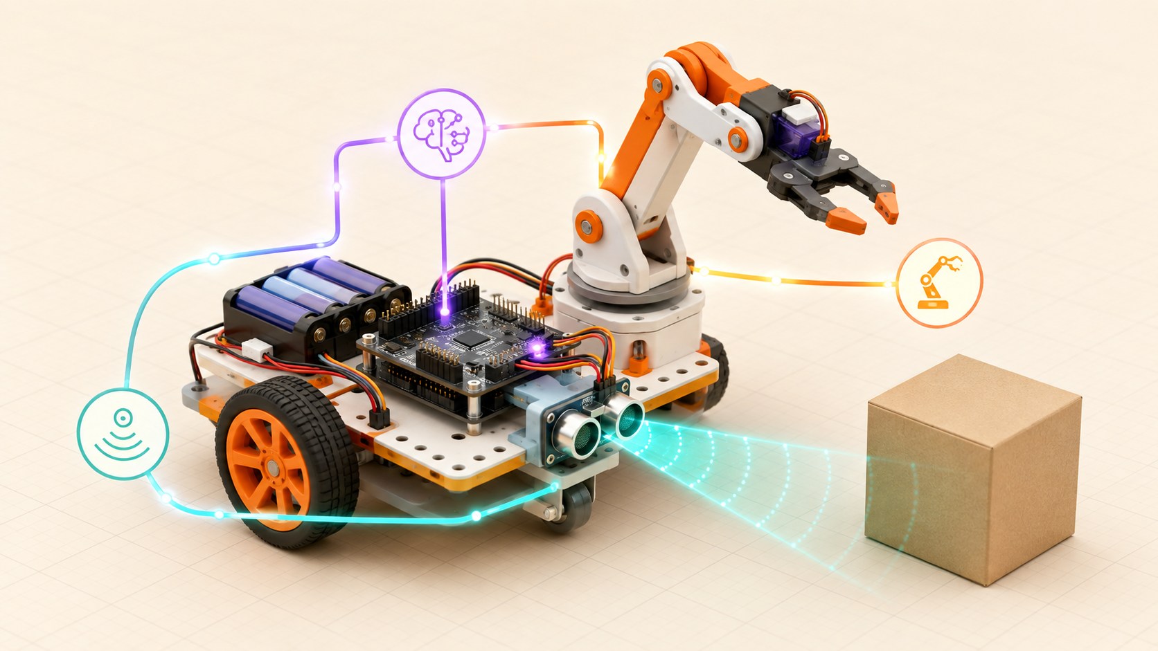
Three-dimensional educational model of a mobile robot sensing a box and controlling its wheels and arm
Concept overview · generated for this Academy4Tech lesson
Start here

See the system, then build it.

You do not need an expensive robot to begin. Paper models, simulations and small motor kits can teach the same system ideas.

01Identify the sensing, computing and acting parts of a robot
02Explain feedback using a simple control loop
03Plan a robot task as testable behaviours
04Measure whether the robot actually meets its goal
Your progress Keep your learning momentum going

0 of 4 sessions complete

Interactive 3D learning studio

Robot systems studio

Inspect a complete sense–decide–act loop, then tune how strongly the controller corrects an error.

Interactive system model · loads on request Poster mode
Explore the system in 3D Inspect the labelled subsystems and watch their modelled process. The lesson flow beside it is a separate conceptual sequence unless it explicitly names the same subsystem. The poster remains available if WebGL is unsupported.
Selected lesson · conceptual flow

Sense, decide, act

What makes a machine a robot?

Step 1 of 4 · Environment

Step through this lesson’s conceptual sequence here. Inspect the separate 3D subsystem model below it to understand the system’s structure.

3D subsystem inspector · 4 model parts
Mini experiment

Change one variable. Predict first, then test.

Find a stable correction between 0.6× and 1.2×.

0.8×
Live result Move the control to test your prediction

Find a stable correction between 0.6× and 1.2×.

Every highlighted 3D group corresponds to a labelled system part. A slider changes the model only when that relationship can be represented faithfully; otherwise the geometry stays still and the live calculation explains the effect. The model simplifies scale and geometry, so use the lesson’s safety notes, measurements and official documentation when building a real system.

01
Session 1 · 20 min

Sense, decide, act

What makes a machine a robot?

Understand it

A useful robot has sensors that measure the environment, a controller that processes those measurements, and actuators that change the world. The controller repeats this loop many times each second. A remote-controlled car acts, but adding distance sensing and an automatic stopping rule makes it behave robotically.

Interactive concept flow

Step 1 of 4 Environment

Choose a step to inspect it, or run the complete sequence.

Sequence progress
1 / 4
Picture it

A useful analogy

Think of crossing a road: your eyes sense traffic, your brain decides when it is safe, and your legs act.

Apply it

Worked example

A distance sensor measures 18 cm. The controller compares that value with a 25 cm safety limit and commands both wheel motors to stop.

Try it
  1. Choose a familiar robot such as a vacuum or automatic door.
  2. List what it senses, what decisions it makes and what moves.
  3. Draw arrows to close the loop back to the environment.
Quick checkWhy is a motor not a sensor?

Answer: A motor changes the physical world, so it is an actuator. A sensor measures the world and sends information to the controller.

02
Session 2 · 25 min

Motion and mechanisms

How does a robot turn electrical energy into movement?

Understand it

Motors create rotation. Wheels, gears, belts and linkages transform that rotation into useful motion. Gear reduction trades speed for torque. Robot arms use joints, while mobile robots often vary the speed of left and right wheels to turn.

Interactive concept flow

Step 1 of 4 Electrical energy

Choose a step to inspect it, or run the complete sequence.

Sequence progress
1 / 4
Picture it

A useful analogy

A bicycle gear makes climbing easier by trading wheel speed for more turning force.

Apply it

Worked example

If the left wheel turns slowly and the right wheel turns quickly, a two-wheel robot curves left.

Try it
  1. Roll two bottle caps together as model wheels.
  2. Hold one still while moving the other.
  3. Predict and sketch the direction the model would turn.
Quick checkWhat does gear reduction usually increase?

Answer: It usually increases torque while reducing output speed.

03
Session 3 · 25 min

Feedback and control

How can a robot correct its own mistakes?

Understand it

Open-loop control sends a command without checking the result. Closed-loop control measures the result, finds the error between target and measurement, then corrects the command. Feedback helps a robot handle slopes, battery changes and small disturbances.

Interactive concept flow

Step 1 of 4 Target

Choose a step to inspect it, or run the complete sequence.

Sequence progress
1 / 4
Picture it

A useful analogy

When steering a bicycle, you keep looking ahead and make many tiny corrections rather than choosing one handlebar angle forever.

Apply it

Worked example

A robot should face 90°, but its sensor reads 82°. The controller sees an 8° error and keeps turning until the error is small.

Try it
  1. Ask a partner to draw a line while looking once, then while continuously looking.
  2. Compare the two results.
  3. Identify which attempt used feedback.
Quick checkWhat is error in a control loop?

Answer: Error is the difference between the desired target and the measured result.

04
Session 4 · 30 min

Build and test behaviours

How do engineers make a robot dependable?

Understand it

Complex tasks become manageable when split into behaviours such as start, follow, avoid, stop and recover. Engineers define a measurable success condition, test one behaviour at a time, record failures, and change only one variable before testing again.

Interactive concept flow

Step 1 of 4 Define success

Choose a step to inspect it, or run the complete sequence.

Sequence progress
1 / 4
Picture it

A useful analogy

A sports team practises passes and set plays separately before playing a full match.

Apply it

Worked example

For obstacle avoidance, define success as stopping at least 20 cm from a box in 9 of 10 trials on two floor surfaces.

Try it
  1. Write a four-state plan for a delivery robot.
  2. Add one failure case, such as a blocked path.
  3. Choose one number that proves success.
Quick checkWhy change one variable at a time?

Answer: It makes the cause of an improvement or failure easier to identify.

Beyond the guided sessions

Explore the whole Robotics field

The guided sessions teach the foundations. This map widens the view across 8 important tracks, with explanations, practice prompts, knowledge checks, and official sources for deeper study.

Build robots from safe mechanisms and electronics through sensing, control, navigation, manipulation, and responsible autonomy.

Field map 0 of 8 tracks explored
Open a track to add it to your journey.
  1. Foundation Robot systems and safety
    Track overview

    A robot combines interacting subsystems in a repeated sense-decide-act cycle, so safety must be designed into the whole system.

    Core concepts

    Four ideas to understand

    1. sense-think-act loop

      Sensors observe the robot and its surroundings, control software chooses a response, and actuators change the physical world. The cycle repeats fast enough to react to new conditions.

    2. robot subsystems

      Structure, power, sensing, computation, actuation, and communication each have a job and an interface. A failure at one interface can affect the entire robot.

    3. coordinate frames

      A coordinate frame defines an origin and axes for describing position and orientation. Transformations let the robot relate measurements made in its body, sensor, tool, and world frames.

    4. workspace risk checks

      A risk check identifies hazards, estimates exposure and severity, then adds guards, limits, warnings, or stop functions. ISO 10218-1 applies specifically to industrial-robot design; it is a useful reference, not a safety certification or a complete rulebook for classroom and mobile robots.

    Check your thinking What are the three stages of the basic robot loop?
    Answer

    Sense the current state, decide what to do, and act on the physical system.

  2. Foundation Mechanics and motion
    Track overview

    Robot motion depends on geometry, forces, transmissions, and contact with the environment.

    Core concepts

    Four ideas to understand

    1. links and joints

      Links are rigid bodies and joints constrain how neighboring links move, such as rotation or sliding. Their arrangement determines the robot degrees of freedom.

    2. torque and load

      Torque is the turning effect of force and grows with perpendicular distance from a joint. Motors and structures must handle the payload plus acceleration, gravity, and a safety margin.

    3. gears and transmissions

      A transmission trades speed for torque and carries motion from an actuator to a joint or wheel. Backlash, efficiency, and gear ratio affect accuracy and performance.

    4. friction and traction

      Friction can provide useful grip or waste energy and resist motion. Available traction limits how strongly a mobile robot can accelerate, brake, or turn without slipping.

    Check your thinking How is torque from a perpendicular force calculated?
    Answer

    Multiply the force by its perpendicular distance from the rotation axis.

  3. Applied Power and actuation
    Track overview

    Actuators turn electrical energy into motion, while drivers and protection keep high-current loads away from fragile control electronics.

    Core concepts

    Four ideas to understand

    1. DC and servo motors

      A DC motor provides continuous rotation controlled mainly by voltage and current. A servo combines a motor, feedback, and a controller to target a commanded position or speed.

    2. motor drivers

      A motor driver switches current that a controller pin cannot safely supply; an H-bridge can also reverse a DC motor. Its voltage, continuous current, peak current, and heat limits must match the load.

    3. battery capacity

      Capacity estimates available charge, but useful run time also depends on current demand, discharge rate, voltage limits, and losses. Motors can draw much more current when starting or stalled.

    4. current protection

      Fuses, current limiting, suitable wire, and flyback paths reduce damage from shorts and inductive voltage spikes. Power should be disconnected before rewiring.

    Check your thinking Why should a motor not be powered directly from a microcontroller output pin?
    Answer

    A motor can demand more current and create larger voltage spikes than the logic pin can safely handle.

  4. Applied Sensing the world
    Track overview

    Sensors provide imperfect evidence, so a robot must sample, calibrate, filter, and interpret measurements rather than treat them as exact truth.

    Core concepts

    Four ideas to understand

    1. distance sensors

      Ultrasonic, infrared, lidar, and depth sensors infer range using different physical signals. Surface material, angle, lighting, echoes, and minimum range can change their readings.

    2. wheel encoders

      Encoders count wheel or shaft movement to estimate speed and distance. Missed counts, wheel diameter error, and slip cause the estimate to drift over time.

    3. inertial measurement

      An IMU measures acceleration and angular rate, and may also measure magnetic field. Integrating noisy data estimates motion but accumulates error unless corrected by other observations.

    4. calibration and noise

      Calibration maps raw values to known quantities and estimates offset or scale error. Filtering can reduce random variation, but excessive smoothing also delays real changes.

    Check your thinking Why does an encoder-only position estimate usually drift?
    Answer

    Small counting, wheel-size, and slip errors accumulate each time motion is integrated.

  5. Applied Feedback control
    Track overview

    Feedback compares measured behavior with a target and adjusts commands to reduce the error while respecting physical limits.

    Core concepts

    Four ideas to understand

    1. open-loop control

      Open-loop control sends a command without measuring whether the desired result occurred. It is simple but cannot correct disturbances or model error.

    2. closed-loop feedback

      A closed loop measures output, computes target minus measurement, and changes its command from that error. Sensor quality and update timing strongly affect stability.

    3. PID response

      Proportional action reacts to current error, integral action accumulates past error, and derivative action responds to how quickly error changes. Gains are tuned together to balance speed, overshoot, and noise.

    4. limits and saturation

      Real motors cannot exceed voltage, speed, force, or travel limits. Controllers should clamp commands and prevent integral windup when the actuator is saturated.

    Check your thinking What value does a feedback controller normally try to reduce?
    Answer

    The error between the target value and the measured value.

  6. Advanced Navigation and planning
    Track overview

    A mobile robot estimates where it is, represents nearby space, chooses a route, and continually reacts as the world changes.

    Core concepts

    Four ideas to understand

    1. odometry

      Odometry estimates incremental motion from wheels, visual features, or inertial sensors. It is locally useful but drifts, so global observations are needed for correction.

    2. mapping and localization

      Mapping builds a representation of obstacles or landmarks, while localization estimates the robot pose within it. SLAM tackles both when neither map nor pose is initially known.

    3. path planning

      A global planner searches for a feasible route through a map, and a local controller turns that route into near-term motion commands. Costs can represent distance, clearance, and robot constraints.

    4. obstacle avoidance

      Fresh sensor data updates nearby hazards so the robot can slow, re-route, or stop. Avoidance must include the full robot footprint and braking distance, not only its center point.

    Check your thinking How do global planning and local control differ?
    Answer

    Global planning chooses a route through the map; local control produces immediate motion while reacting to nearby conditions.

  7. Advanced Arms and manipulation
    Track overview

    Manipulation connects joint geometry, collision-aware planning, grasp design, and controlled contact with objects.

    Core concepts

    Four ideas to understand

    1. forward kinematics

      Forward kinematics computes the tool pose from known joint values and link geometry. It answers where the end effector will be for one robot configuration.

    2. inverse kinematics

      Inverse kinematics finds joint values that can produce a requested tool pose. A target may have several solutions, no solution, or a solution near an unstable singularity.

    3. end effectors

      Grippers, suction cups, and tools interact with the task object. Selection depends on shape, surface, payload, required force, and what failure would do.

    4. compliant motion

      Compliance allows controlled movement or force when contact differs from the plan. Mechanical elasticity or force feedback can reduce impact and help with insertion tasks.

    Check your thinking What is the input to forward kinematics?
    Answer

    Joint values and the robot link geometry; the result is the end-effector pose.

  8. Advanced Reliable autonomy
    Track overview

    Reliable autonomous behavior needs explicit task logic, well-defined software interfaces, layered testing, and safe ways for people to intervene.

    Core concepts

    Four ideas to understand

    1. state machines and behavior trees

      These structures divide a mission into states or reusable behaviors with clear transitions and failure paths. They make recovery logic easier to inspect than one large control loop.

    2. robot middleware

      Middleware lets sensing, planning, and control components exchange typed data and lifecycle status. Interfaces should state timing, units, frames, ownership, and failure behavior.

    3. simulation testing

      Simulation can repeat normal, boundary, and fault scenarios without risking hardware. It does not reproduce every contact, sensor, or timing effect, so staged physical tests remain necessary.

    4. human-aware behavior

      A robot should make its intent and operating state understandable, preserve safe separation, and yield when uncertainty rises. Accessible stop and handoff procedures keep human authority clear.

    Check your thinking Why is a successful simulation not enough to approve a physical robot?
    Answer

    The simulator cannot perfectly reproduce hardware faults, contact, sensor noise, timing, or the real workspace.

Verified next steps

Official references

Use these primary sources to extend the explanations and check current guidance.

  1. International Organization for Standardization ISO 10218-1:2025 — Robotics — Safety requirements — Part 1: Industrial robots
  2. Northwestern University Modern Robotics: Mechanics, Planning, and Control
  3. ros-controls project ros2_control
  4. Arduino Transistor Motor Control
  5. Open Navigation LLC Navigation Concepts
  6. PickNik Concepts — MoveIt Documentation
Three-project build pathway

Learn Robotics by making it work.

Start small, combine the ideas, then complete a measured challenge. Every project includes a material list, four build milestones, evidence to collect, and a safe next step.

  1. Starter · 60–90 minutes Sense–Decide–Act Tabletop Course Learn one dependable building block Create a small obstacle course and make a simulated or low-voltage classroom rover react to three clearly defined sensor zones. The project turns the robot loop into something learners can observe, predict, and explain.
    What you will learn

    Learning goals

    • Identify the sensing, control, actuation, power, and structure subsystems.
    • Translate a simple mission into input–decision–output rules.
    • Compare a prediction with the rover’s measured behavior and explain any difference.
    Prepare

    Materials and tools

    • Browser-based rover simulator or a teacher-approved low-voltage rover
    • Cardboard, removable tape, and three lightweight obstacle markers
    • Ruler or tape measure
    • Printed observation table or spreadsheet
    Build sequence

    Four milestones

    1. Draw a subsystem diagram and label the direction of information and energy flow.

    2. Build three wide, low-risk zones for continue, turn, and stop, then predict the rover response in each.

    3. Run at least five trials from marked start positions and record detection distance, action, and outcome.

    4. Revise one threshold or rule, repeat the same trials, and explain whether the evidence improved.

    Prove it works

    Evidence to collect

    • A labelled sense–decide–act diagram uses the correct subsystem names and signal directions.
    • The rover completes at least four of five repeatable trials without touching an obstacle.
    • A before-and-after table connects the changed rule to an observable result rather than a guess.
  2. Builder · 2–3 hours Twin-Wheel Feedback Lab Connect multiple ideas into a working system Build a simulation that keeps a two-wheel robot travelling straight even when one wheel is weaker. Learners collect encoder evidence, tune a bounded correction, and see why feedback outperforms a fixed command.
    What you will learn

    Learning goals

    • Calculate wheel-speed error from target and encoder measurements.
    • Implement a bounded proportional correction without exceeding actuator limits.
    • Evaluate rise time, steady error, overshoot, and sensitivity to disturbances.
    Prepare

    Materials and tools

    • Web, Python, or robotics simulator with independently controlled wheels
    • Starter controller template or pseudocode sheet
    • Graphing tool or spreadsheet
    • Test plan with fixed starting conditions and disturbances
    Build sequence

    Four milestones

    1. Measure the path and left/right wheel speeds under equal open-loop commands.

    2. Compute speed error and add a clamped proportional correction to each wheel command.

    3. Test at least four gains under the same weak-wheel disturbance and graph both speed traces.

    4. Select a gain using stated performance criteria and document what happens near saturation.

    Prove it works

    Evidence to collect

    • The controller code or block diagram shows target, measurement, error, gain, correction, and limits.
    • Results compare at least one open-loop and three closed-loop trials using the same disturbance.
    • The chosen controller reduces steady heading error without unsafe oscillation or hidden saturation.
  3. Challenge · 4–6 hours Resilient Delivery-Robot Mission Test, measure, and improve a complete solution Design a simulated delivery mission that maps a small environment, plans between stations, responds to a blocked route, and enters a safe recovery state when localization or sensing becomes unreliable.
    What you will learn

    Learning goals

    • Relate coordinate frames, localization, mapping, global planning, and local control.
    • Represent mission behavior with inspectable states and explicit failure transitions.
    • Use repeatable scenario evidence to distinguish successful autonomy from a lucky run.
    Prepare

    Materials and tools

    • Robot navigation simulator with mapping and obstacle support
    • Provided or self-made indoor map with two delivery stations
    • State-machine or behavior-tree diagramming tool
    • Scenario log and screen-recording tool
    Build sequence

    Four milestones

    1. Define map, robot footprint, coordinate frames, goals, speed limits, stopping rule, and success metrics.

    2. Complete a baseline map-and-deliver run while logging pose, route, and mission-state changes.

    3. Inject a blocked corridor, noisy range data, and a temporary localization fault in separate repeatable tests.

    4. Add re-planning, timeout, safe-stop, and human-handoff behavior, then run the complete test matrix again.

    Prove it works

    Evidence to collect

    • The robot reaches both stations in at least three repeat baseline runs without violating its clearance rule.
    • Each injected fault produces the documented recovery, safe-stop, or handoff state rather than uncontrolled motion.
    • The final report includes a state diagram, annotated route, logs, limitations, and one unresolved risk.
Words to know

Build your vocabulary.

Sensor
A device that measures a physical quantity.
Actuator
A device that creates movement or another physical change.
Controller
The hardware and software that turns measurements into decisions.
Feedback
Using a measured result to correct the next action.
Torque
Turning force around an axis.
Behaviour
One testable robot action or response.
Work safely

Before you power or move anything.

  • Disconnect power before changing wiring.
  • Keep fingers, hair and loose clothing away from gears and wheels.
  • Use low-voltage educational hardware and an appropriate motor driver.
Keep studying

Official documentation.

These lessons simplify the first ideas. Use the original documentation when building, checking details or moving to the next level.

Continue learning

Related Academy4Tech content.

ProjectAdvanced

WildeBeest Pro

A complete dual-ROS autonomous-robot reference stack joining CAD, simulation, navigation, sensor fusion, a safety-oriented Arduino controller and an operator dashboard.

ROS 2 JazzyPythonC++Arduino

Learn by building.

Choose a real project, identify the smallest subsystem you can test, and document what the measurement tells you.