01Sense
Robot inputs
LiDAR, camera and GNSS join encoder, IMU and ultrasonic telemetry from the base controller.
/scan · /camera/image_raw · /gps/fix 
A complete dual-ROS autonomous-robot reference stack joining CAD, simulation, navigation, sensor fusion, a safety-oriented Arduino controller and an operator dashboard.
Launch the CAD-derived 3D model, select a subsystem or step through a simulated command. Every action reveals how sensing, planning and wheel control connect.
Interactive system explorer ready.
LiDAR/ranging, camera, IMU, GNSS, side-encoder feedback and ultrasonic sensing turn the physical world into timestamped observations.
Educational browser model: the 3D geometry is derived from the supplied assembly, while sensing and motion are explanatory simulations. Nothing here connects to the physical robot. Real motion requires supervised commissioning, validated limits and an independent hardware emergency stop.
Select a route through the real repository stack. Each view highlights only the layers involved.
LiDAR, camera and GNSS join encoder, IMU and ultrasonic telemetry from the base controller.
/scan · /camera/image_raw · /gps/fix Wheel odometry and IMU data feed robot_localization; mapping or localization owns map → odom.
/wheel/odometry · /odometry/filtered Nav2 and SLAM Toolbox build or use a map, check obstacles and produce a bounded motion request.
/cmd_vel/navigation Navigation, web remote and joystick commands meet at one priority-and-timeout boundary.
twist_mux → /cmd_vel The bridge checks state, units, firmware identity and framed serial data before forwarding motion.
BOOT identity · CRC-16/CCITT-FALSE A 50 Hz base loop closes wheel speed, samples local sensors and stops after 300 ms without a valid command.
CMD ↔ ODOM · IMU · RANGE Two side channels drive the skid-steer chassis while odometry, battery state and diagnostics return upstream.
L298N → motors · /diagnostics Sensor messages support localization and Nav2 planning. The resulting request still passes through command arbitration, the fail-closed base bridge and the Arduino watchdog before motor output is allowed.
This guide follows the implemented repository from software-only simulation to supervised hardware commissioning. Repository-tested software and unverified physical readiness are identified separately.
WildeBeest Pro is an open reference implementation for a compact four-wheel skid-steer autonomous robot. It connects the complete engineering chain: mechanical CAD, a ROS robot description, sensor drivers, localization, mapping, navigation, command arbitration, a serial base bridge, Arduino motor firmware, simulation, an operator dashboard, testing and commissioning documentation.
The repository now provides a complete software-side reference implementation with equivalent public interfaces for ROS 2 and ROS 1. Its software, firmware, deterministic mocks, documentation and simulation models are implemented and host-tested. That does not mean the physical machine is commissioned: the as-built wiring, power system, encoder installation, calibrated dimensions, stopping behavior and emergency-stop hardware still require measured validation before motor power is connected.
| Status | What it means |
|---|---|
| Implemented and host-tested | ROS workspaces, Arduino firmware, protocol, mock controller, simulation, navigation configuration, dashboard, documentation and automated checks |
| Ready to explore now | Docker-based ROS 2 or ROS 1 mock robot, native simulation, source code, CAD and this browser-based 3D explainer |
| Still requires physical evidence | Electrical/mechanical commissioning, exact sensor and driver selection, wiring inspection, calibration, fault injection and staged motion tests |
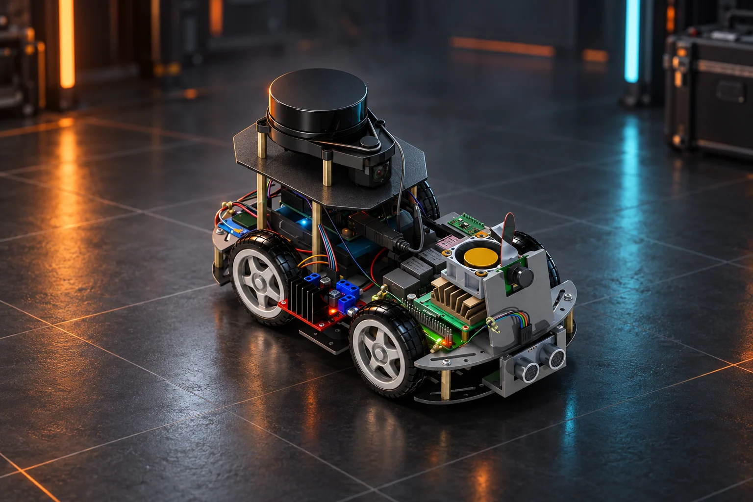
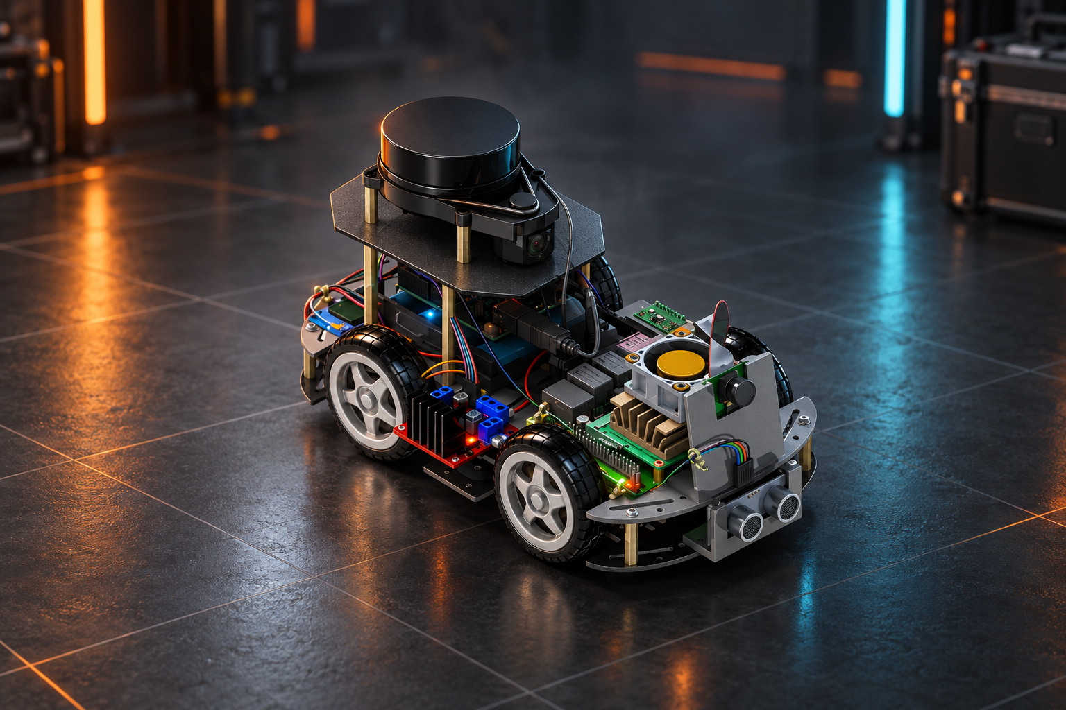
The interactive controls on this page operate only the educational browser model. They do not connect to a robot. The hero artwork is AI-enhanced presentation imagery; the launchable 3D model is derived from the supplied mechanical assembly and is the better source for spatial understanding.
The ROS 2 Jazzy workspace is the recommended path for new development. It includes the robot description and TF tree, a real-or-mock base bridge, command multiplexing, local state estimation, optional GNSS fusion, Nav2, SLAM Toolbox, sensor launch files and a Gazebo Harmonic simulation. The supported native profile is Ubuntu 24.04 on a compatible workstation or arm64 computer.
The ROS 1 Noetic workspace preserves the same frame, topic and safety concepts with Catkin, move_base, gmapping and Gazebo Classic. It exists for compatibility and migration; ROS 1 Noetic itself is end-of-life and should not be the default for a new deployment.
The shared platform adds:
rosbridge_suite;The camera path currently publishes standard images for future perception work; the repository does not claim a completed AI inference or computer-vision model.
The software diagram above can trace three routes through the implementation. In normal autonomous operation, the full loop is:
robot_localization combines the appropriate velocity and inertial measurements into /odometry/filtered. SLAM or localization supplies the world-to-local transform when enabled./cmd_vel/navigation for a goal.twist_mux selects one fresh source by priority, applies the software-stop lock and publishes the stable /cmd_vel interface.wildebeest_base accepts only supported linear-x and angular-z motion, requires the expected controller boot identity, checks serial framing and fails closed across disconnects or restarts.This separation is intentional: navigation understands destinations and obstacles, while the microcontroller owns bounded-latency hardware I/O. Neither replaces a correctly rated, independent physical emergency stop.
| Physical or simulated input | Visual key | ROS interface | How it is used |
|---|---|---|---|
| 2D LiDAR | Orange #E69F00 |
/scan |
SLAM, localization and obstacle layers; the final scanner model, baud rate and scan direction must match the installed hardware |
| IMX219 camera | Sky blue #56B4E9 |
/camera/image_raw, /camera/camera_info |
Vision experiments and perception input; it is not in the base motion safety path |
| MPU-6050 | Rose #CC79A7 |
/imu/data_raw |
Angular-rate and acceleration input for local state estimation; it has no magnetometer |
| NEO-6M GNSS | Yellow #F0E442 |
/gps/fix, /gps/vel where available |
Optional outdoor global fusion after datum, quality and heading strategy are validated |
| HC-SR04 front range | Vermillion #D55E00 |
/range/front |
Complementary near-field obstacle input; a timeout must not be interpreted as clear space |
| Side wheel encoders | Teal site aid | /wheel/odometry, /joint_states |
Raw local motion and wheel visualization after counts, signs, radius and effective track are calibrated |
| Base controller | Neutral system color | /battery_state, /diagnostics |
Link, firmware, watchdog, stop, CRC, sensor and battery health |
The first five colors are the project’s shared, color-blind-conscious sensor key across ROS 1, ROS 2, RViz, Gazebo, the CAD showcase and this site. They identify hardware only; they never indicate live health or status. The frame tree follows standard mobile-robot conventions: map → odom → base_link, with fixed child frames for the wheels, LiDAR, camera and optical frame, IMU, GNSS and front ultrasonic sensor. Each dynamic transform has one owner. Duplicate TF or velocity publishers are treated as configuration faults, because a plausible RViz view can still hide a broken control graph.
The primary ROS 2 launch routes every motion source through twist_mux:
| Input | Priority | Intended source |
|---|---|---|
/cmd_vel/navigation |
10 | Nav2 controller |
/cmd_vel/remote |
40 | Browser dashboard or supervised remote operator |
/cmd_vel/teleop |
50 | Local joystick/keyboard teleoperation |
/wildebeest/estop |
255 lock | Dashboard and software-safety request |
The output is /cmd_vel, consumed by the base bridge. The stack deliberately layers its stopping behavior:
Releasing a stop does not replay an old command. The production ROS bridge and firmware start fail-closed, verify WILDEBEEST_BASE protocol version 1, and require a deliberate release followed by a fresh command. CRC failures, malformed fields and out-of-range commands are rejected and do not refresh the motion watchdog.
The quickest reproducible route is Docker Desktop on Windows or macOS, or Docker Engine with Compose on Linux. Git LFS is needed only when you want the complete CAD corpus.
git clone https://github.com/Tech2morrow/Wildebeest_Pro.git
cd Wildebeest_Pro
git lfs install
git lfs pull
docker compose --profile ros2 up --build ros2-mock
The ros2-mock profile launches the full ROS 2 graph with a deterministic in-process base controller. It exercises framing, watchdog behavior, odometry, TF, localization and command flow without a USB serial device or energized motor hardware. Stop it with Ctrl+C.
To exercise the compatibility stack instead:
docker compose --profile ros1 up --build ros1-mockMock mode is a functional integration environment, not a physics or electrical model. It cannot validate traction, current draw, real sensor noise, wiring, heat or stopping distance.
On Ubuntu 24.04 with ROS 2 Jazzy installed:
./scripts/bootstrap.sh ros2
./scripts/build.sh ros2
source ros2_ws/install/setup.bash
ros2 launch wildebeest_bringup robot.launch.py use_sim:=true
For the Gazebo Harmonic world and RViz:
ros2 launch wildebeest_gz simulation.launch.py use_rviz:=trueThe real-hardware launch makes sensor drivers opt-in, so an absent camera, GNSS receiver or LiDAR cannot block base commissioning:
ros2 launch wildebeest_bringup robot.launch.py \
  transport:=serial serial_port:=/dev/wildebeest-base \
  start_camera:=true start_gps:=true start_lidar:=true
The concept files do not identify the exact production LiDAR, so the package and executable are configurable launch arguments. The included default targets rplidar_ros; builders must change its port, baud, scan mode and driver settings to match the label and datasheet of the actual scanner.
On the legacy Ubuntu 20.04 / ROS 1 Noetic profile:
./scripts/bootstrap.sh ros1
./scripts/build.sh ros1
source ros1_ws/devel/setup.bash
roslaunch wildebeest_bringup robot.launch use_sim:=true
The legacy physics demo is:
roslaunch wildebeest_simulation demo.launchROS 1 uses different build and launch syntax, but it keeps the same public intent for commands, odometry, sensing, frames and stops. Treat it as a migration/reference environment rather than a long-term supported base for a new robot.
The Noetic bootstrap deliberately skips gscam because it is not resolved by the current Noetic rosdep index. Camera launch therefore defaults to off; install and validate a Jetson-compatible gscam build separately before opting in.
The repository includes a responsive, dependency-free dashboard that works with ROS 1 or ROS 2 through rosbridge_suite:
node dashboard/dev-server.mjsOpen http://127.0.0.1:8088/ for the local interface. A live robot also needs a trusted rosbridge endpoint, normally on port 9090. The dashboard publishes only to /cmd_vel/remote, so it remains behind the priority and timeout multiplexer; it must never be remapped directly to the base command input.
The UI renders local scan geometry and freshness for odometry, LiDAR, IMU, GNSS, front range and battery. Its on-screen stop is a useful supervisory control, but it is not safety-rated and cannot replace the physical motor-power disconnect.
| Path | What a builder will find |
|---|---|
ros2_ws/ |
Primary Jazzy base, bringup, description, Nav2, SLAM and Gazebo packages |
ros1_ws/ |
Noetic-compatible base, bringup, description, navigation and simulation |
firmware/wildebeest_base/ |
Arduino Uno motor/encoder controller, protocol and native-test sources |
config/robot.toml |
Version-neutral frames, geometry, motion limits, serial and sensor defaults |
dashboard/ |
rosbridge mission-control interface and local development server |
docs/ |
MkDocs readiness, architecture, safety, operations, calibration and test handbook |
BOM/ |
Commissioning workbook with a deliberate blocked gate for unresolved safety items |
3D_Mechanical_Design/ |
SolidWorks Pack-and-Go assembly, STEP exchange model and placed STL corpus |
tools/ |
Shared protocol codec, mock MCU, robot doctor, CAD renderer and tests |
For a deeper technical walk-through, read the repository’s system architecture, ROS interface contract, operations runbook and acceptance test plan.
The authoritative native assembly is 3D_Mechanical_Design/P&G Wildebeest_Pro/Wildebeest_Pro_P&G.SLDASM. A matching Wildebeest_Pro_P&G.STEP file supports CAD tools that do not open SolidWorks assemblies. Copy or open the whole Pack-and-Go directory so referenced parts, subassemblies, appearances and scenes remain resolvable.
The mechanical corpus also contains 595 placed STL components and more than 2.8 million source triangles. Serving those files directly would make the page slow and fragile, so the explorer uses a reduced, materialized GLB derived from the supplied exports. It preserves the whole chassis, major electronics, separately pivoted wheels and color-separated sensor groups while removing tiny fasteners and internal connector detail that does not improve browser-scale understanding.
The planned-route button moves the digital chassis and rolls its actual wheel nodes. LiDAR sweeps, camera cones, ultrasonic rings, telemetry and route motion are educational overlays rather than sensor recordings, physics evidence or a verified real-robot motion profile.
The repository centralizes nominal values for repeatable software behavior:
| Parameter | Repository default | Commissioning rule |
|---|---|---|
| Wheel radius | 0.033622 m | Measure loaded effective radius on the built robot |
| Wheel-centre track | 0.121843 m | Tune effective skid-steer track on the operating surface |
| Wheelbase | 0.117150 m | Verify against the assembled chassis |
| Encoder counts | 600 counts/revolution | Replace with the selected encoder and decoding convention |
| Maximum linear speed | 0.45 m/s | Reduce until stopping distance and stability are measured |
| Maximum angular speed | 1.8 rad/s | Validate on each approved surface and payload |
| Serial link | 115200 baud | Use a stable device name and prove reconnect behavior |
| Firmware command timeout | 300 ms | Verify command-to-output-disable time under load |
These figures make software and tests deterministic; the repository marks geometry and voltage thresholds as unverified for the physical build. In particular, KY-040 modules are not dependable wheel-odometry encoders. The real drive needs suitable encoder hardware, mounting and signal integrity before closed-loop navigation can be claimed.
Do not jump directly from a green build to autonomous floor motion. The included handbook uses evidence gates:
Any unexpected motion, lost stop layer, battery damage, recurring brownout, encoder disagreement, stale critical sensor or loose mechanical part is a stop-work condition. WildeBeest Pro is a research and education platform, not a safety-certified vehicle.
The checked-in verification system is intentionally broad, but readers should understand its boundary. CI exercises the shared protocol, dashboard, manifests, documentation, static workspace checks, firmware compilation and both ROS container builds. Each container probe now requires a validated controller BOOT handshake, ready diagnostics and live /wheel/odometry; merely keeping a launch process alive is not enough. The PlatformIO native Unity firmware-test sources remain a separate developer run, and hardware-in-the-loop or physical acceptance results are not supplied by a green host build. The standalone helper mock is useful for tooling experiments, but release decisions should use the production ROS mock, real firmware tests and the staged acceptance plan together.
On Windows:
python -m pip install -r requirements-ci.txt
.\scripts\test.ps1
On Linux:
python3 -m pip install -r requirements-ci.txt
./scripts/test.sh
Download the complete main-branch project archive (.zip) or open WildeBeest Pro on GitHub. The public main branch is the source of truth for the download. Review its README, commit history and configuration record before following instructions so your software, CAD and commissioning evidence refer to the same revision.
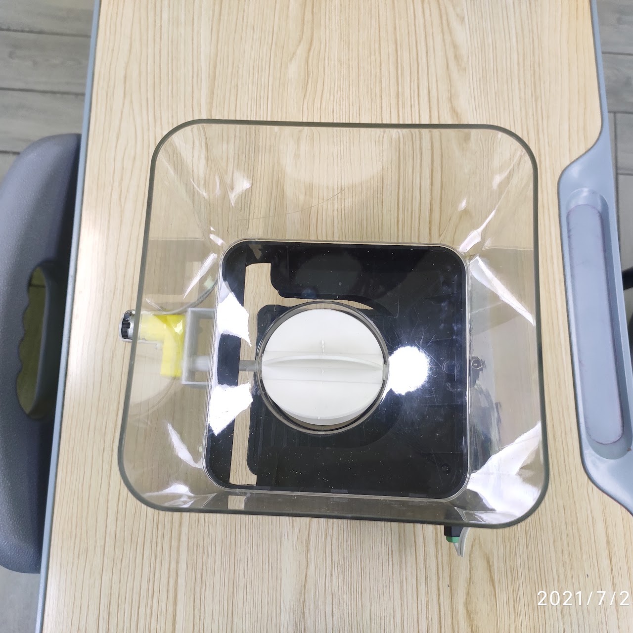
An Arduino-based timed feeder concept with three configurable feeding times, an LCD and keypad input.
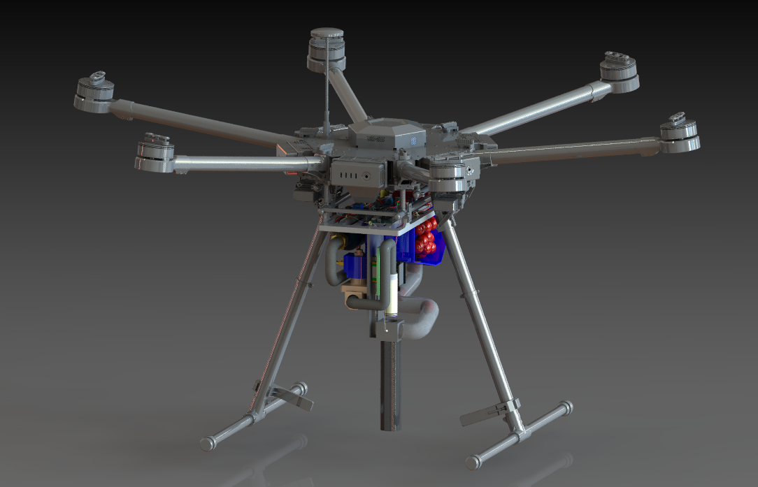
A concept and prototype for a DJI M600 Pro planting payload using a 3D-printed seed container and pneumatic firing mechanism.
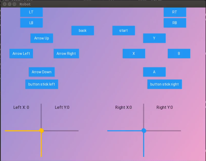
A Python and KivyMD interface that visualizes Logitech F710 joystick data carried through ROS.