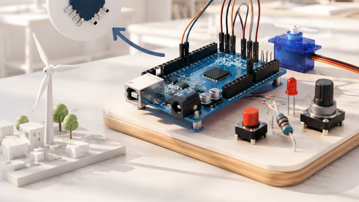
You can understand Arduino without treating it as magic or memorizing a long list of terms. Start with one simple mental model, connect each part to an everyday example, and then add the technical details that make the system dependable.
The big idea: Arduino makes microcontroller experiments approachable by joining a programmable board, a simple code structure and reusable libraries.
Build one input and one output first. Confirm each part works before combining them.
Why this matters
Arduino makes invisible electrical signals visible. A few lines of code can read a button, measure a sensor and control a light or motor—making it an excellent first step into physical computing.
By the end of this guide, you will be able to:
- Explain the setup-and-loop structure of a sketch
- Wire and control a digital input and output safely
- Read an analog signal and create PWM output
- Separate logic power from higher-current actuator power
The goal is not only to recognize the words. It is to explain the system, predict what it will do, and design a small test that produces evidence.
1. Board, pins and sketches
The question: What happens when an Arduino sketch runs?
A microcontroller runs one program repeatedly. setup() runs once after start or reset; loop() then repeats. Pins can be configured as inputs or outputs. The uploaded program continues without a full desktop operating system.
Think of it like this: Opening a classroom happens once, but checking the room and doing tasks repeats throughout the day.
A concrete example
Configure an LED pin in setup(), then turn it on and off with delays in loop().
The flow: Power or reset → setup once → loop repeatedly → Pin changes
A small code example
const int ledPin = 9;

void setup() {
  pinMode(ledPin, OUTPUT);
}

void loop() {
  digitalWrite(ledPin, HIGH);
  delay(500);
  digitalWrite(ledPin, LOW);
  delay(500);
}
Read it from top to bottom and ask what information enters, what rule is applied, and what result comes out.
Try it yourself
- Open the built-in Blink example.
- Point to setup and loop.
- Predict what changing the delay will do.
Quick check — How many times does setup() normally run?
Once after power-up or reset.
2. Digital input and output
The question: How does a controller read a button and control an LED?
Digital signals use two logical states, HIGH and LOW. Inputs must not float between states, so a pull-up or pull-down resistor gives the pin a known default. An LED needs a series resistor to limit current.
Think of it like this: A door is treated as open or closed, even though the handle moves through many positions.
A concrete example
Use INPUT_PULLUP for a button: an unpressed button reads HIGH and a pressed button connected to ground reads LOW.
The flow: Button state → Digital input → Decision → LED output
Try it yourself
- Draw a button using the internal pull-up.
- Trace the current path when pressed.
- Write a truth table for button and LED states.
Quick check — Why does an LED need a resistor?
The resistor limits current so the LED and controller pin are not damaged.
3. Analog input and PWM
The question: How can a digital controller work with changing signals?
An analog-to-digital converter turns a voltage range into a number. PWM rapidly switches a digital output to control average energy. PWM can dim an LED or command some motor drivers, but it is not a true analog voltage.
Think of it like this: A fast light switch can make a lamp appear dimmer when it spends less time on during each cycle.
A concrete example
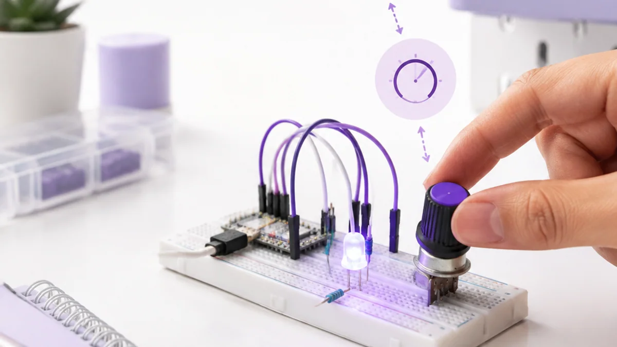
Map a potentiometer reading to a PWM duty value so turning the knob changes LED brightness.
The flow: Changing voltage → ADC number → Map range → PWM duty
Try it yourself
- Sketch low, middle and high PWM waveforms.
- Mark the on-time in each.
- Predict relative LED brightness.
Quick check — What does 25% PWM duty mean?
The output is on for about one quarter of each repeating cycle.
4. Sensors, actuators and safe power
The question: Why should motors not be powered directly from a pin?
Sensors usually use small currents, but motors and servos can demand much more than a microcontroller pin supplies. Use a driver or suitable external supply, share ground where the circuit requires it, and protect against voltage spikes from inductive loads.
Think of it like this: A small doorbell button can signal a powerful gate motor, but it should not carry the motor current itself.
A concrete example
A light sensor tells the controller it is dark; the controller signals a transistor driver that powers a lamp.
The flow: Sensor → Controller logic → Driver → Separate load power
Try it yourself
- Label logic and load current paths on a motor diagram.
- Circle the shared reference connection.
- Add a safe power-off step before rewiring.
Quick check — What is the driver’s job?
It lets a low-power control signal safely switch or regulate a higher-current load.
Put the ideas together: Build a responsive night light
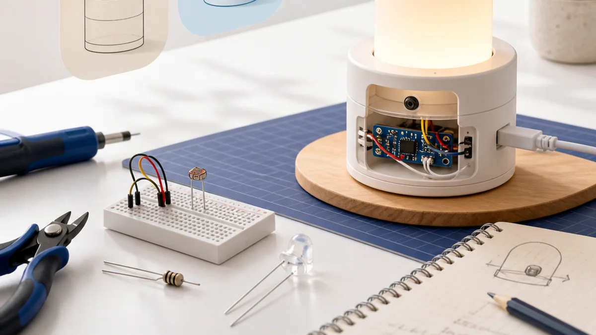
Plan or build a low-voltage light that brightens as the room becomes darker.
Your build plan
- Read a light-dependent sensor.
- Map the reading to LED PWM output.
- Print readings for calibration.
- Test bright, medium and dark conditions.
Evidence to keep
- Wiring diagram
- Commented sketch
- Three calibration readings
- A short test result
An engineer does not stop at “it worked once.” Keep the diagram, record the conditions, repeat the test, and note what changed between attempts.
Important safety and quality notes
- Remove USB or battery power before rewiring.
- Use a resistor with every ordinary LED.
- Never connect motors or mains-powered loads directly to an I/O pin.
The examples in this article are educational models. Check component ratings, manufacturer instructions, local rules and appropriate supervision before using real hardware.
Vocabulary without the jargon wall
| Term | Plain-language meaning |
|---|---|
| Sketch | An Arduino program. |
| GPIO | General-purpose input/output pins. |
| Pull-up | A resistor that gives an input a known HIGH default. |
| ADC | A converter that represents an analog voltage as a number. |
| PWM | Pulse-width modulation: controlling average output with timed pulses. |
| Driver | A circuit that safely controls a load requiring more power. |
What to remember
Arduino makes microcontroller experiments approachable by joining a programmable board, a simple code structure and reusable libraries. The professional habit behind the technology is equally important: define the result, observe the system, measure what happened, and improve one thing at a time.
Continue with the full Arduino learning path for the structured sessions, or explore the sources below when you are ready for deeper technical detail.
Sources and further learning
- Arduino learning resources — Arduino
- Arduino programming reference and examples — Arduino
- Built-in examples — Arduino
Explore PWM brightness control
Pulse-width modulation switches an output quickly. Duty cycle is the percentage of each cycle spent on.
Move a slider to explore the model.
Remember: this is a simplified learning model, not a hardware design or safety calculator. Real systems also include limits, noise, timing and failure handling.