
Intermediate · visual course

Unmanned Aerial Vehicles

A drone stays in the air by controlling forces many times each second, then combines sensing, estimation and planning to fly a safe mission.

Flight controlSensorsVision 4 guided sessions 8 skill tracks 3 example projects
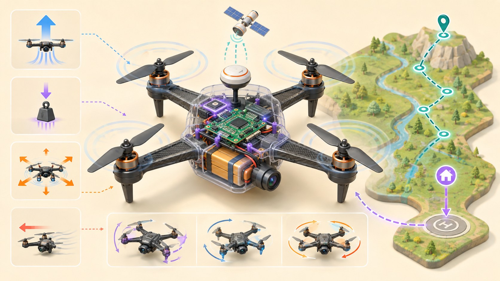
Three-dimensional educational quadcopter showing rotors, flight controller, sensors, camera and a safe waypoint mission
Concept overview · generated for this Academy4Tech lesson
Start here

See the system, then build it.

Begin with diagrams and simulation. Real flight needs trained supervision, a safe location and the rules for the country where you fly.

01Explain lift, weight, thrust and drag during hover and motion
02Trace the flight-control feedback loop from sensors to rotor speed
03Plan a waypoint mission with boundaries and recovery actions
04Create a safe test plan using simulation, checklists and flight logs
Your progress Keep your learning momentum going

0 of 4 sessions complete

Interactive 3D learning studio

Flight-control studio

Balance four rotors, onboard sensing and corrective control before planning a mission.

Interactive system model · loads on request Poster mode
Explore the system in 3D Inspect the labelled subsystems and watch their modelled process. The lesson flow beside it is a separate conceptual sequence unless it explicitly names the same subsystem. The poster remains available if WebGL is unsupported.
Selected lesson · conceptual flow

Forces, rotors and attitude

How can four rotors lift and steer one aircraft?

Step 1 of 4 · Rotor thrust

Step through this lesson’s conceptual sequence here. Inspect the separate 3D subsystem model below it to understand the system’s structure.

3D subsystem inspector · 4 model parts
Mini experiment

Change one variable. Predict first, then test.

Find the simplified hover band from 48% to 58%.

52%
Live result Move the control to test your prediction

Find the simplified hover band from 48% to 58%.

Every highlighted 3D group corresponds to a labelled system part. A slider changes the model only when that relationship can be represented faithfully; otherwise the geometry stays still and the live calculation explains the effect. The model simplifies scale and geometry, so use the lesson’s safety notes, measurements and official documentation when building a real system.

01
Session 1 · 20 min

Forces, rotors and attitude

How can four rotors lift and steer one aircraft?

Understand it

Each rotor accelerates air downward and produces an upward thrust force. In a steady hover, total upward thrust balances the drone’s weight. Increasing all rotors makes the drone climb. Changing rotor speeds by different amounts rolls, pitches or yaws the aircraft. To move forward, the drone tilts so part of its thrust points forward while enough still points upward.

Interactive concept flow

Step 1 of 4 Rotor thrust

Choose a step to inspect it, or run the complete sequence.

Sequence progress
1 / 4
Picture it

A useful analogy

Balance a tray on your hands: raise both hands to lift it, or raise one side more to tilt it toward a direction.

Apply it

Worked example

A quadcopter pitches forward by changing rotor thrust so the whole frame tilts. The angled thrust now has a forward part, so the drone accelerates ahead.

Try it
  1. Draw a side view of a hovering drone.
  2. Add equal upward thrust and downward weight arrows.
  3. Tilt the thrust arrow and split it into upward and forward parts.
Quick checkWhat must be true for a drone to hover at constant height?

Answer: Its total upward thrust must balance its weight, with no unbalanced vertical force.

02
Session 2 · 25 min

The flight-control loop

How does a drone notice and correct a tilt?

Understand it

The flight controller reads gyroscopes and accelerometers in an inertial measurement unit, then may combine barometer, compass and GNSS data. An estimator turns noisy measurements into a best estimate of attitude, height and position. The controller compares that estimate with the requested state and adjusts motor commands to reduce the error.

Interactive concept flow

Step 1 of 4 Sensors measure

Choose a step to inspect it, or run the complete sequence.

Sequence progress
1 / 4
Picture it

A useful analogy

Carrying a full cup, your inner ear and eyes notice a tilt and your hands make many tiny corrections before water spills.

Apply it

Worked example

A gust creates a 6° roll error. The controller briefly increases thrust on the low side and reduces it on the high side until the measured roll returns near the target.

Try it
  1. List which sensor could help estimate rotation, height and outdoor position.
  2. Invent one bad reading for each.
  3. Explain why comparing several sensors can reveal a problem.
Quick checkWhy does the controller use an estimated attitude instead of one raw sensor value?

Answer: Raw measurements contain noise and limitations; an estimator combines evidence over time to produce a more useful state estimate.

03
Session 3 · 25 min

Modes, waypoints and boundaries

How does a drone turn a goal into a route?

Understand it

A flight mode decides which quantities the pilot or autopilot controls. An autonomous mission can connect waypoints with heights, speeds and actions. The navigator turns the next waypoint into position targets, while lower control loops stabilize the aircraft. A geofence, home point and return or land action limit what happens when the plan cannot continue.

Interactive concept flow

Step 1 of 4 Mission goal

Choose a step to inspect it, or run the complete sequence.

Sequence progress
1 / 4
Picture it

A useful analogy

A map gives the next destination, a driver follows the road, and guardrails keep the vehicle inside a safer region.

Apply it

Worked example

A survey mission climbs to a safe height, visits four points around a field, returns above the launch area and lands only after the landing zone is clear.

Try it
  1. Sketch a four-waypoint survey route.
  2. Add a home point and no-go boundary.
  3. Write responses for low battery, lost control link and poor position data.
Quick checkDoes GNSS position automatically prevent a drone from hitting a tree?

Answer: No. GNSS estimates position; obstacle detection and avoidance need suitable sensors, software and a safe operating plan.

04
Session 4 · 30 min

Test safely and learn from logs

How do engineers reduce risk before a real flight?

Understand it

Testing should move from a diagram to software-in-the-loop simulation, restrained bench checks with propellers removed, and only then supervised flight in a legal open area. A pre-flight checklist confirms structure, battery, sensors, home position, weather, people and failsafes. Logs turn a surprising event into evidence that can be inspected.

Interactive concept flow

Step 1 of 4 Simulate

Choose a step to inspect it, or run the complete sequence.

Sequence progress
1 / 4
Picture it

A useful analogy

A theatre rehearses individual scenes, then a full run, before performing in front of an audience.

Apply it

Worked example

Before take-off, verify control direction and return settings in simulation, inspect every propeller, check the battery, confirm the flight area and name the person who can stop the test.

Try it
  1. Create a ten-item pre-flight checklist.
  2. Design one simulated link-loss test and its expected result.
  3. Choose three log values that would explain an unstable hover.
Quick checkWhy remove propellers during most bench tests?

Answer: An unexpected motor command cannot turn the propellers into fast-moving blades that injure people or damage equipment.

Beyond the guided sessions

Explore the whole Unmanned Aerial Vehicles field

The guided sessions teach the foundations. This map widens the view across 8 important tracks, with explanations, practice prompts, knowledge checks, and official sources for deeper study.

Understand multirotor flight, energy, estimation, control, missions, maintenance, and lawful risk-managed operation from simulation to supervised tests.

Field map 0 of 8 tracks explored
Open a track to add it to your journey.
  1. Foundation Flight forces, frames, and motion
    Track overview

    A drone moves because thrust and aerodynamic effects produce forces and moments relative to body, local, and world coordinate frames.

    Core concepts

    Four ideas to understand

    1. Weight, thrust, drag, and lift

      Weight acts toward Earth, rotors create thrust, and air motion creates drag and other aerodynamic forces. Hover requires force balance, while acceleration requires a net force.

    2. Body axes and attitude

      Roll, pitch, and yaw describe rotation about body axes. Frame conventions and rotation order must be explicit because the same numbers can otherwise describe different attitudes.

    3. Force and moment control

      Changing total rotor thrust controls vertical force, while differences between rotors create roll, pitch, and yaw moments. The mixer translates desired motion into actuator commands.

    4. Stability and disturbance

      A multirotor is not passively self-leveling in every condition, so feedback must correct attitude continuously. Wind, payload shift, and ground effect change the required control effort.

    Check your thinking What must be true of vertical forces in a steady hover?
    Answer

    Upward thrust balances weight, so the net vertical force and vertical acceleration are approximately zero.

  2. Foundation Airframe, propulsion, and energy
    Track overview

    Frame geometry, motors, propellers, electronic speed controllers, and batteries must operate as one matched system with structural and electrical margin.

    Core concepts

    Four ideas to understand

    1. Airframe and rotor geometry

      Arm length, mass distribution, stiffness, and rotor placement affect control authority and vibration. Correct motor order and propeller direction are essential to the mixer.

    2. Motor, propeller, and ESC matching

      Propeller size and pitch set motor load, while the ESC must handle voltage, current, commutation, and cooling. Use validated combinations and never approach spinning propellers.

    3. Battery limits and state

      Cell chemistry, voltage, capacity, discharge current, temperature, and internal resistance constrain flight. State of charge is an estimate and voltage sag grows under high load.

    4. Mass and endurance budget

      Payload, frame, wiring, and battery mass all increase required thrust and energy. Reserve policy should use measured consumption and landing margin rather than an ideal capacity number.

    Check your thinking Why is battery nameplate capacity not equal to safe usable flight energy?
    Answer

    Voltage sag, discharge limits, temperature, aging, efficiency, and required landing reserve reduce the usable amount.

  3. Applied Avionics, sensors, and estimation
    Track overview

    The flight controller combines correctly mounted, calibrated, and time-aligned sensors to estimate attitude, velocity, position, and health.

    Core concepts

    Four ideas to understand

    1. IMU and vibration control

      Gyroscopes measure angular rate and accelerometers measure specific force; both have bias and noise. Rigid orientation plus suitable vibration isolation prevents corrupted estimates.

    2. Altitude and heading sensors

      Barometers infer pressure altitude and magnetometers help heading, but prop wash, temperature, metal, and current can disturb them. Placement and calibration must match the airframe.

    3. GNSS and external positioning

      Satellite or external systems provide position with environment-dependent accuracy and outages. A fix indicator alone does not guarantee integrity for the planned maneuver.

    4. State estimation and innovation checks

      An estimator blends sensor predictions and observations with uncertainty. Innovation or consistency checks reveal when a measurement disagrees strongly enough to reject or flag it.

    Check your thinking Why should a magnetometer be kept away from high-current wiring?
    Answer

    Current produces magnetic fields that can bias heading measurements, especially as motor load changes.

  4. Applied Feedback control and flight modes
    Track overview

    Nested feedback loops turn pilot or mission demands into stable rates, attitude, velocity, and position while respecting actuator and estimator limits. Parameter names and procedures are autopilot-specific, so do not mix PX4 and ArduPilot instructions.

    Core concepts

    Four ideas to understand

    1. Rate and attitude loops

      The fast inner loop controls angular rate; an outer loop commands rates to achieve attitude. Inner-loop performance must be established before tuning slower outer behavior.

    2. PID effects and saturation

      Proportional action responds to error, integral action removes steady bias, and derivative action adds damping but reacts to noise. Saturated actuators cannot obey further demand and need anti-windup handling.

    3. Flight-mode authority

      Manual, stabilized, altitude, position, and mission modes rely on different sensors and automation. The operator must know what each mode controls and how authority changes after a fault.

    4. Tuning evidence

      Command-response logs reveal overshoot, oscillation, delay, saturation, and disturbance rejection. Change one controlled variable at a time and preserve a known-safe configuration.

    Check your thinking Why should a position loop not be tuned before the attitude loop is stable?
    Answer

    Position control depends on the faster attitude system accurately producing the commanded acceleration.

  5. Applied Navigation, geofencing, and missions
    Track overview

    Mission software converts goals into routes and actions while checking position quality, terrain, obstacles, energy, and limits throughout execution.

    Core concepts

    Four ideas to understand

    1. Waypoints and mission state

      A waypoint carries position, altitude reference, acceptance behavior, and sometimes an action. Mission state must handle pause, resume, skip, abort, and restart deterministically.

    2. Altitude and terrain references

      Altitude may be relative to home, mean sea level, terrain, or a local frame. Mixing references can create a hazardous vertical command even when the number looks reasonable.

    3. Geofence and return planning

      A geofence constrains where the aircraft should operate, while return behavior needs a safe route, altitude, destination, and energy reserve. Neither replaces physical obstacle awareness.

    4. Mission validation

      Review route geometry, airspace, weather, links, position quality, battery, contingencies, and land sites before arming. Rehearse unexpected transitions in simulation.

    Check your thinking Why can a return-to-home feature still create a collision?
    Answer

    Its programmed climb and route may not account for every obstacle, position error, terrain reference, or changing environment.

  6. Advanced Links, payloads, and responsible autonomy
    Track overview

    Command links, telemetry, payload data, and autonomous decisions add capability while introducing loss-of-control, privacy, bandwidth, and human-oversight risks.

    Core concepts
    1. Command and telemetry links

      Control and status channels have finite range, latency, bandwidth, and interference tolerance. Monitor link quality and define behavior for degraded or lost communication.

    2. Payload integration

      A payload changes mass, balance, drag, power demand, electromagnetic environment, and data flow. Recalculate limits and revalidate the aircraft after each meaningful change.

    3. Autonomy confidence and handover

      Detection or planning confidence is not certainty, especially outside training conditions. Define when the system slows, stops, returns, or transfers control to a prepared operator.

    4. Data minimization and privacy

      Collect only data needed for the stated mission, restrict access and retention, and avoid recording people or property unnecessarily. Legal and community expectations vary by location.

    Check your thinking Why must a new camera payload trigger more than a software check?
    Answer

    It also changes mass, balance, drag, power, interference, endurance, privacy, and potentially regulatory conditions.

  7. Advanced Simulation, logs, maintenance, and test progression
    Track overview

    Safe development progresses from models and bench checks through controlled tests, using logs and configuration records to find faults and manage airworthiness.

    Core concepts

    Four ideas to understand

    1. SITL, HIL, and reality gap

      Software-in-the-loop tests algorithms quickly; hardware-in-the-loop adds real flight electronics and timing. Neither reproduces every aerodynamic, RF, structural, or sensor condition.

    2. Flight-log analysis

      Logs connect commands, estimates, sensor health, actuator output, battery, and faults on one timeline. Preserve parameters, firmware, hardware identity, and event time with each record.

    3. Inspection and configuration control

      Propellers, fasteners, wiring, frame, batteries, and sensors degrade or move. A configuration baseline and inspection schedule make changes and recurring defects visible.

    4. Graduated testing

      Progress from simulation to propeller-free bench work, then only to purpose-built guarded propulsion tests and controlled flight under qualified supervision. Expand one risk dimension at a time with abort criteria.

    Check your thinking What information should accompany a flight log to make comparison meaningful?
    Answer

    At minimum, the aircraft hardware, firmware, parameters, payload, test conditions, timeline, and operator observations.

  8. Advanced Operational safety and regulation
    Track overview

    A technically working drone may still be unsafe or unlawful; every operation needs local authorization, competent people, airspace checks, and rehearsed contingencies.

    Core concepts

    Four ideas to understand

    1. Local legal category and airspace

      Registration, pilot competence, operating category, altitude, proximity, identification, and authorization rules depend on jurisdiction. ICAO models and EASA rules are references, not substitutes for the local aviation authority.

    2. Preflight and pre-arm discipline

      Confirm aircraft condition, configuration, sensors, battery, control direction, mission, site, weather, people, and alerts before arming. Do not bypass a failed check without understanding and formally accepting the risk.

    3. Failsafes and emergency roles

      Battery, link, position, geofence, and system faults need tested actions such as land, return, hold, or operator intervention. Flight termination is irreversible and belongs only in an engineered risk-control scheme with validated safety devices; it is not a routine recovery mode.

    4. Risk assessment and records

      Identify hazards, exposed people and property, severity, likelihood, controls, and residual risk for the exact operation. Keep maintenance, approvals, incidents, and configuration evidence as required.

    Check your thinking Can an ICAO model rule or EASA guide by itself authorize a flight anywhere?
    Answer

    No; the rules and permissions of the aviation authority responsible for the actual location and operation control.

Verified next steps

Official references

Use these primary sources to extend the explanations and check current guidance.

  1. NASA Four Forces of Flight
  2. PX4 Autopilot PX4 v1.17 — Assembling a Multicopter
  3. PX4 Autopilot PX4 v1.17 — Safety (Failsafe) Configuration
  4. ArduPilot ArduPilot Copter — Pre-Arm Safety Checks
  5. PX4 Autopilot PX4 v1.17 — Using PX4's Navigation Filter (EKF2)
  6. PX4 Autopilot PX4 v1.17 — Multicopter PID Tuning Guide
  7. PX4 Autopilot PX4 v1.17 — Log Analysis using Flight Review
  8. International Civil Aviation Organization ICAO Model UAS Regulations
  9. European Union Aviation Safety Agency Easy Access Rules for Unmanned Aircraft Systems — Revision from June 2026
Three-project build pathway

Learn Unmanned Aerial Vehicles by making it work.

Start small, combine the ideas, then complete a measured challenge. Every project includes a material list, four build milestones, evidence to collect, and a safe next step.

  1. Starter · 3–4 hours Explore hover forces and energy in simulation Learn one dependable building block Use a multicopter simulator and flight logs to connect mass, weight, total thrust, throttle, acceleration, and estimated energy without arming a physical aircraft.
    What you will learn

    Learning goals

    • Draw force diagrams in the correct vehicle and world frames.
    • Distinguish balanced hover from acceleration and understand why thrust margin matters.
    • Use logged evidence to compare predictions with a simplified flight model.
    Prepare

    Materials and tools

    • PX4 SITL with a supported multicopter simulator and ground-control interface
    • Plotting or flight-log review tools
    • A worksheet for mass, gravity, thrust, hover throttle, duration, and assumptions; no physical drone
    Build sequence

    Four milestones

    1. Draw and label lift/thrust, weight, drag, and relevant frame directions for rest, hover, climb, and descent.

    2. Predict weight and required ideal hover thrust for the baseline simulated vehicle, including units and assumptions.

    3. Run repeatable hover segments at three simulated masses and record attitude, altitude, vertical velocity, actuator demand, and energy indicators.

    4. Compare prediction with logs, explain discrepancies, and identify a conservative mass or energy limit for this simulation model.

    Prove it works

    Evidence to collect

    • Force diagrams and calculations use consistent frames, signs, units, and distinguish force from power or energy.
    • Three logged trials show a defensible relationship among mass, hover actuator demand, and simulated energy use.
    • The conclusion states simulator assumptions and does not claim measured real-world flight endurance or certified performance.
  2. Builder · 6–9 hours Design a geofenced failsafe mission Connect multiple ideas into a working system Configure and verify a short SITL mission whose preflight gates, geofence, lost-link, battery, navigation, and mission-failure responses are visible in logs.
    What you will learn

    Learning goals

    • Treat pre-arm checks and failsafes as layered risk controls rather than obstacles to bypass.
    • Relate mission states, geofence geometry, link health, energy margin, estimator status, and recovery actions.
    • Create an expected-event timeline before injecting a fault.
    Prepare

    Materials and tools

    • PX4 SITL, supported simulator, and ground-control station
    • A simple virtual test area with home point, geofence, and four mission waypoints
    • Flight-log review tools and a fault-injection worksheet; no physical aircraft
    Build sequence

    Four milestones

    1. Define the simulated operating volume, mission path, home point, minimum margins, preflight gates, and expected terminal state.

    2. Configure the mission and conservative geofence, link-loss, low-battery, and navigation-failure actions; review every change against matching-version documentation.

    3. Run a clean baseline followed by separate link-loss, geofence, low-energy, and invalid-navigation cases without stacking faults.

    4. Build a state timeline from logs for each run and decide whether every detection, transition, response, and final state met the written expectation.

    Prove it works

    Evidence to collect

    • The baseline completes inside the defined virtual volume with a consistent home position and no unexplained preflight warning.
    • Each isolated fault has a logged trigger, configured response, bounded trajectory, and unambiguous end state.
    • A configuration snapshot and test matrix let another learner reproduce the same behavior on the documented software version.
  3. Challenge · 10–14 hours Qualify an inspection mission digital twin Test, measure, and improve a complete solution Engineer a simulation-only inspection mission that balances coverage, image geometry, navigation quality, geofencing, energy reserve, fault response, and evidence-based go/no-go decisions.
    What you will learn

    Learning goals

    • Decompose a mission into aircraft, estimator, controller, navigation, link, payload, environment, and operational constraints.
    • Measure route coverage and margins while varying wind, sensor quality, link availability, and energy.
    • Use logs and a risk register to decide whether a virtual design is ready for further controlled testing—not for flight.
    Prepare

    Materials and tools

    • PX4 SITL with supported simulation world and ground-control software
    • A virtual structure or waypoint volume, simulated camera footprint assumptions, and log-analysis tools
    • Version-controlled mission/configuration files, test matrix, risk register, and reporting template
    Build sequence

    Four milestones

    1. Write inspection coverage, image overlap, standoff, altitude, geofence, energy-reserve, link, and mission-abort requirements with stated assumptions.

    2. Design the virtual route and camera actions, validate frame and estimator health, and complete repeated no-fault baselines with fixed software versions.

    3. Run a structured matrix for wind, positioning degradation, magnetic disturbance model, link loss, blocked waypoint, and reduced energy separately.

    4. Analyze logs, map coverage and minimum margins, classify each run, update the risk register, and issue a simulation-stage go/no-go recommendation.

    Prove it works

    Evidence to collect

    • Baseline repetitions meet declared virtual coverage, overlap, standoff, containment, and reserve limits with quantified variation.
    • Fault trials show detection and bounded mission behavior, with estimator/control evidence supporting every pass or fail decision.
    • The final review clearly separates demonstrated simulation evidence, untested real-world assumptions, regulatory needs, and next-stage controls.
Words to know

Build your vocabulary.

Thrust
Force produced by accelerating air, used by the rotors to support and move the drone.
Attitude
The aircraft orientation described by roll, pitch and yaw.
IMU
An inertial measurement unit containing motion sensors such as gyroscopes and accelerometers.
Estimator
Software that combines measurements to calculate the most likely vehicle state.
Waypoint
A planned position, often with height and action information, in a mission.
Failsafe
A configured response intended to reduce risk when a fault or limit is detected.
Work safely

Before you power or move anything.

  • Learn and test in simulation before operating hardware.
  • Remove propellers and disconnect power before bench wiring or configuration.
  • Use trained adult supervision, keep people clear and inspect lithium batteries for damage.
  • Follow the current aviation rules and airspace requirements where the flight takes place; the FAA link is a United States example.
Keep studying

Official documentation.

These lessons simplify the first ideas. Use the original documentation when building, checking details or moving to the next level.

Continue learning

Related Academy4Tech content.

Learn by building.

Choose a real project, identify the smallest subsystem you can test, and document what the measurement tells you.