
Beginner · visual course

Electronics

Electronics controls energy and information through complete circuits whose voltage, current and resistance can be measured.

MultimeterCircuitsSensors 4 guided sessions 8 skill tracks 3 example projects
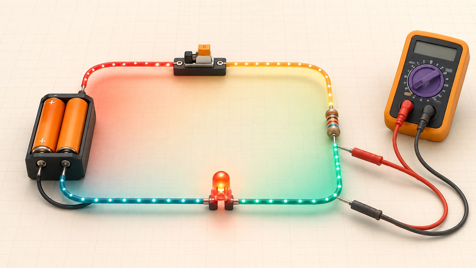
Three-dimensional low-voltage circuit with battery, switch, resistor, LED and multimeter probes
Concept overview · generated for this Academy4Tech lesson
Start here

See the system, then build it.

Start with batteries or current-limited bench supplies. Never experiment directly with wall electricity.

01Explain voltage, current and resistance in a closed circuit
02Calculate simple values with Ohm’s law
03Compare series and parallel connections
04Use a multimeter with correct mode and connection
Your progress Keep your learning momentum going

0 of 4 sessions complete

Interactive 3D learning studio

Circuit behaviour studio

Follow voltage, current and resistance around a safe low-voltage LED circuit.

Interactive system model · loads on request Poster mode
Explore the system in 3D Inspect the labelled subsystems and watch their modelled process. The lesson flow beside it is a separate conceptual sequence unless it explicitly names the same subsystem. The poster remains available if WebGL is unsupported.
Selected lesson · conceptual flow

Voltage, current and resistance

What moves through a circuit, and what controls it?

Step 1 of 4 · Potential difference

Step through this lesson’s conceptual sequence here. Inspect the separate 3D subsystem model below it to understand the system’s structure.

3D subsystem inspector · 4 model parts
Mini experiment

Change one variable. Predict first, then test.

Protect the example LED with 220–680 Ω.

330 Ω
Live result Move the control to test your prediction

Protect the example LED with 220–680 Ω.

Every highlighted 3D group corresponds to a labelled system part. A slider changes the model only when that relationship can be represented faithfully; otherwise the geometry stays still and the live calculation explains the effect. The model simplifies scale and geometry, so use the lesson’s safety notes, measurements and official documentation when building a real system.

01
Session 1 · 20 min

Voltage, current and resistance

What moves through a circuit, and what controls it?

Understand it

Voltage is potential difference between two points. Current is the rate of charge flow through a path. Resistance opposes current. For an ohmic component, V = I × R connects the three quantities.

Interactive concept flow

Step 1 of 4 Potential difference

Choose a step to inspect it, or run the complete sequence.

Sequence progress
1 / 4
Picture it

A useful analogy

Water pressure resembles voltage, flow rate resembles current, and a narrow pipe resembles resistance—but the analogy has limits.

Apply it

Worked example

Across a 330 Ω resistor at 3.3 V, ideal current is 3.3 ÷ 330 = 0.010 A, or 10 mA.

Try it
  1. Cover one value in the Ohm’s-law triangle.
  2. Solve for current with 5 V and 1 kΩ.
  3. Check that units become milliamps.
Quick checkCan current flow through an open circuit?

Answer: Ideally no. The broken path prevents continuous charge flow.

02
Session 2 · 25 min

Series and parallel

How does connection shape change circuit behaviour?

Understand it

Series components share one current path, and their voltage drops add. Parallel branches share the same two end nodes, so each branch has the same voltage. Adding a parallel branch lowers equivalent resistance and increases total source current.

Interactive concept flow

Step 1 of 4 Source

Choose a step to inspect it, or run the complete sequence.

Sequence progress
1 / 4
Picture it

A useful analogy

A single queue is series; several checkout lanes between the same entrance and exit are parallel.

Apply it

Worked example

Two 1 kΩ resistors in series total 2 kΩ; the same two in parallel equal 500 Ω.

Try it
  1. Draw two lamps in series and parallel.
  2. Mark equal current or equal voltage.
  3. Predict what happens if one lamp opens.
Quick checkWhat quantity is equal across ideal parallel branches?

Answer: The voltage across each branch is the same.

03
Session 3 · 25 min

Components shape signals

Why are different electronic components needed?

Understand it

Resistors limit current and divide voltage. Capacitors store electric-field energy and smooth change. Diodes favour one current direction, while transistors use a small control signal to switch or regulate a larger path. Sensors change an electrical property with the environment.

Interactive concept flow

Step 1 of 4 Signal or power

Choose a step to inspect it, or run the complete sequence.

Sequence progress
1 / 4
Picture it

A useful analogy

A toolbox has different tools because gripping, cutting and measuring are different jobs.

Apply it

Worked example

A resistor protects an LED, while a transistor allows a microcontroller to control a load requiring more current.

Try it
  1. Match five components to jobs.
  2. Choose a component for motor switching.
  3. Explain why a resistor alone is not a motor driver.
Quick checkWhat does a capacitor store?

Answer: Energy in an electric field, associated with separated charge.

04
Session 4 · 30 min

Measure and troubleshoot safely

How does a multimeter become part of the circuit?

Understand it

Voltage is measured across two points with the meter in parallel. Current is measured by opening the path and inserting the meter in series. Resistance is measured only on an unpowered circuit. Begin with the correct port and range.

Interactive concept flow

Step 1 of 4 Choose quantity

Choose a step to inspect it, or run the complete sequence.

Sequence progress
1 / 4
Picture it

A useful analogy

A pressure gauge connects across a pipe section, while a flow meter must become part of the flow path.

Apply it

Worked example

To check an LED resistor, disconnect power, isolate the component if needed, select resistance and measure across it.

Try it
  1. Draw meter connections for voltage and current.
  2. Circle the dangerous mistake of placing a current-mode meter across a battery.
  3. Write a three-step pre-measurement check.
Quick checkWhy is current mode dangerous across a source?

Answer: The meter presents a very low-resistance path that can cause a large current, damage or injury.

Beyond the guided sessions

Explore the whole Electronics field

The guided sessions teach the foundations. This map widens the view across 8 important tracks, with explanations, practice prompts, knowledge checks, and official sources for deeper study.

Understand, calculate, build, and measure low-voltage circuits from physical quantities through analog, digital, power, and evidence-based troubleshooting.

Field map 0 of 8 tracks explored
Open a track to add it to your journey.
  1. Foundation Voltage, current, resistance, and power
    Track overview

    Electrical quantities describe charge flow and energy transfer; correct units, reference points, and sign conventions turn a circuit sketch into testable predictions.

    Core concepts

    Four ideas to understand

    1. Voltage and reference nodes

      Voltage is a potential difference between two points, so every voltage statement needs a reference. Choosing a ground node simplifies equations but does not change physical current paths.

    2. Current and branches

      Current is the rate of charge flow and is measured through a branch. Its direction is a chosen convention; a negative result means the physical flow is opposite to that choice.

    3. Resistance and Ohm's law

      For an ohmic element, voltage, current, and resistance satisfy V = IR over its valid operating range. Real resistors also have tolerance, power, temperature, and voltage limits.

    4. Power and energy

      Instantaneous electrical power is voltage times current, while energy is power accumulated over time. Under the passive sign convention, positive power means an element absorbs energy and negative power means it delivers energy.

    Check your thinking Can a point in a circuit have an absolute voltage?
    Answer

    No; voltage is always a difference between two points, even when one point is named ground.

  2. Foundation Networks, AC response, and stored energy
    Track overview

    Conservation laws and component models explain DC behavior, sinusoidal steady state, and the time-dependent response of stored electric and magnetic energy.

    Core concepts

    Four ideas to understand

    1. Kirchhoff's laws and equivalents

      KCL applies charge conservation at a node and KVL balances voltage changes around a loop. Series-parallel, Thévenin, and Norton equivalents simplify linear networks as viewed from specified terminals.

    2. AC impedance, RMS, and phase

      Sinusoidal voltage and current have magnitude, frequency, and phase; RMS expresses equivalent heating. Complex impedance combines resistance and reactance so AC dividers and frequency response can be calculated consistently.

    3. Capacitors, RC filters, and transients

      A capacitor stores electric-field energy and its voltage cannot jump without unbounded current. Its reactance falls with frequency, while an RC time constant predicts transient response and RC networks form low-pass or high-pass filters.

    4. Inductors, resonance, and transformers

      An inductor stores magnetic energy and its current cannot jump without unbounded voltage. Inductance with capacitance can resonate, mutual inductance enables transformers, and interrupted coil current needs a safe path.

    Check your thinking Which quantities cannot change instantaneously in ideal capacitors and inductors?
    Answer

    Ideal capacitor voltage and ideal inductor current are continuous at a switching instant.

  3. Applied Diodes, transistors, and switching
    Track overview

    Semiconductor devices use nonlinear behavior to rectify, regulate, amplify, and switch, but their ratings and operating regions must be respected.

    Core concepts

    Four ideas to understand

    1. Diode behavior

      A diode's current-voltage curve is nonlinear and changes with temperature. Rectifier, Schottky, Zener, and light-emitting types are optimized for different jobs.

    2. BJT operating regions

      A BJT uses base drive to control collector current and can act as an amplifier or saturated switch. Forced gain, storage time, and dissipation matter in a switching design.

    3. MOSFET gate and channel

      A MOSFET gate is voltage controlled but must be charged and discharged, so switching needs transient gate current. Use on-resistance at the actual gate voltage, not only threshold voltage.

    4. Safe device operation

      Voltage, current, power, temperature, and transient limits interact through the safe operating area. Protection and thermal design must keep expected and abnormal conditions inside those limits.

    Check your thinking Why is MOSFET threshold voltage not a suitable gate-drive target?
    Answer

    Threshold is specified at tiny channel current; low on-resistance requires the gate voltage used in the datasheet's resistance specification.

  4. Applied Operational amplifiers and analog signals
    Track overview

    Op-amp circuits provide gain, buffering, filtering, and comparison when feedback assumptions, input range, output limits, and bandwidth are all satisfied.

    Core concepts

    Four ideas to understand

    1. Negative feedback

      Negative feedback drives the input difference small while the amplifier remains in its linear region. The familiar ideal rules are consequences of feedback, not universal device facts.

    2. Inverting and non-inverting gain

      Resistor ratios set closed-loop gain for common configurations, and input impedance differs between them. Component tolerance and bias currents create real gain and offset error.

    3. Input and output limits

      Common-mode range, rail headroom, output current, and load determine whether an op amp can follow the intended signal. Rail-to-rail labels still require checking conditions in the datasheet.

    4. Bandwidth, slew rate, and noise

      Closed-loop gain reduces available bandwidth, slew rate limits large-signal speed, and device plus resistor noise sets a measurement floor. Choose parts from the signal bandwidth and accuracy budget.

    Check your thinking When is the ideal rule that both op-amp inputs have nearly equal voltage valid?
    Answer

    When negative feedback is active and the amplifier is operating within its input, output, speed, and supply limits.

  5. Applied Digital logic and timing
    Track overview

    Digital circuits interpret analog voltages as logic states, so thresholds, timing, fan-out, and transitions determine whether Boolean intent survives in hardware.

    Core concepts

    Four ideas to understand

    1. Logic levels and noise margin

      Input thresholds and guaranteed output levels define valid LOW and HIGH ranges. Noise margin is the remaining voltage allowance between those guarantees.

    2. Combinational and sequential logic

      Combinational outputs depend on present inputs; sequential circuits also store state. Truth tables, state diagrams, and reset behavior make that logic reviewable.

    3. Propagation and setup timing

      Gates and interconnect take time to respond, while flip-flops require data around the clock edge. Violating setup or hold time can produce metastability rather than a reliable bit.

    4. Interfacing logic families

      Check voltage thresholds, output drive, input leakage, edge rate, and power-up state before connecting logic families. A nominal voltage match alone is not enough.

    Check your thinking What does noise margin measure?
    Answer

    It is the guaranteed voltage difference between an output logic level and the receiving input threshold.

  6. Advanced Power conversion, interfaces, and protection
    Track overview

    Useful systems convert and distribute energy, connect unlike circuits, and contain abnormal conditions without degrading the intended signal.

    Core concepts

    Four ideas to understand

    1. Linear and switching regulation

      Linear regulators are simple but dissipate voltage drop as heat; switching converters transfer energy efficiently through timed switches and reactive components. Load, ripple, stability, EMI, and thermal needs guide the choice.

    2. Grounding and level translation

      Shared-reference interfaces need compatible common-mode and logic ranges. Level translators or isolation solve different problems and can have direction, speed, and startup constraints.

    3. Transient protection

      Series impedance, clamping, filtering, fusing, and current limiting divide transient energy safely. A protection part works only if its surge rating and current return path are suitable.

    4. Load and fault budgets

      A power tree should budget average, peak, startup, and fault current for every rail. Include source resistance, wire drop, connector rating, and thermal margin.

    Check your thinking Why can a linear regulator overheat even when its output current is within rating?
    Answer

    Its dissipation is approximately the input-output voltage drop times current, and the package may not remove that heat at the actual ambient temperature.

  7. Applied Measurement practice and lab safety
    Track overview

    An instrument changes the circuit it observes, so safe setup, probe choice, bandwidth, reference connection, and uncertainty are part of every result.

    Core concepts

    Four ideas to understand

    1. Multimeter connection

      Voltage is measured in parallel and current in series with the correct jack and range. An ammeter placed across a source can create a dangerous short circuit.

    2. Oscilloscope probing

      Probe attenuation, compensation, bandwidth, capacitance, and ground lead affect a waveform. Bench-scope ground is commonly earth-referenced, so an incorrect clip location can short the circuit.

    3. Aliasing and triggering

      A sampling display can show a false slower waveform when the rate is insufficient. Stable triggering helps viewing but does not prove that an aliased waveform is real.

    4. Controlled low-voltage work

      De-energize before rewiring, limit available current, protect eyes, and keep exposed mains outside unsupervised student work. Qualified procedures and rated equipment are required for hazardous energy.

    Check your thinking Why can clipping a bench oscilloscope ground to the wrong node cause damage?
    Answer

    The ground lead may be bonded to protective earth, so the clip can force that node to earth and create a high-current short.

  8. Advanced Design verification and troubleshooting
    Track overview

    Engineering confidence comes from requirements, worst-case reasoning, controlled tests, and traceable evidence across normal, boundary, and fault conditions.

    Core concepts

    Four ideas to understand

    1. Requirements and budgets

      Turn goals into measurable ranges for supply, gain, bandwidth, load, temperature, and error. Allocate each limit across components so tradeoffs are visible before building.

    2. Tolerance and corner analysis

      Components vary with tolerance, temperature, bias, and age. Worst-case or statistical analysis tests whether the whole combination still meets its requirement.

    3. Structured fault isolation

      Start from power, reference, reset, clock, and signal flow; compare expected with measured values at boundaries. Change one factor at a time and keep a record.

    4. Verification evidence

      A verification table links every requirement to a method, setup, expected result, actual result, and artifact. Repeatable evidence is stronger than an undocumented demonstration.

    Check your thinking What makes a test result traceable to a design requirement?
    Answer

    The record identifies the requirement, method, setup, configuration, expected limit, measured result, and retained evidence.

Verified next steps

Official references

Use these primary sources to extend the explanations and check current guidance.

  1. National Institute of Standards and Technology SI Units – Electric Current
  2. MIT OpenCourseWare Circuits and Electronics
  3. Analog Devices ADALM1000 SMU Training Topic 17: Basic Op Amp Configurations
  4. Texas Instruments Logic Guide (Rev. AC)
  5. Tektronix Oscilloscope Basics: Waveforms, Graph, & Measurement Reading
Three-project build pathway

Learn Electronics by making it work.

Start small, combine the ideas, then complete a measured challenge. Every project includes a material list, four build milestones, evidence to collect, and a safe next step.

  1. Starter · 2–3 hours Measure an LED circuit like an engineer Learn one dependable building block Predict and measure voltage, current, resistance, and power in a current-limited 5 V LED circuit, then explain why real values differ from ideal calculations.
    What you will learn

    Learning goals

    • Apply polarity, Ohm's law, Kirchhoff's voltage law, and passive-sign power reasoning.
    • Connect a voltmeter in parallel and an ammeter in series without creating a short circuit.
    • Report measured values with units, tolerance, uncertainty, and plausible causes of error.
    Prepare

    Materials and tools

    • Circuit simulator, or an optional 5 V current-limited bench supply
    • Breadboard, LED, 330 Ω and 1 kΩ resistors, leads, and a verified digital multimeter
    • LED and resistor datasheets plus a measurement table
    Build sequence

    Four milestones

    1. Draw the circuit, mark current direction and polarities, and predict current, node voltages, resistor power, and LED power for both resistors.

    2. Simulate each case and reconcile the loop voltage and total supplied/absorbed power using consistent signs.

    3. Optionally build the unpowered circuit, verify meter modes and lead sockets, then power it through a conservative current limit and measure both cases.

    4. Graph predicted versus observed current and brightness, calculate percentage differences, and explain at least three non-ideal effects.

    Prove it works

    Evidence to collect

    • For each resistor, measured or simulated loop voltages agree within a declared tolerance and all values carry correct units.
    • The reported series current is consistent at each component and remains below the LED and resistor ratings.
    • A comparison explains LED forward-voltage variation, resistor tolerance, supply error, and meter burden or model assumptions without forcing perfect agreement.
  2. Builder · 5–7 hours Tune a low-voltage sensor conditioner Connect multiple ideas into a working system Design a single-supply op-amp circuit that maps a small simulated sensor range into an ADC-friendly output while controlling gain, offset, bandwidth, noise, and clipping.
    What you will learn

    Learning goals

    • Derive gain and offset from an input/output range instead of selecting values by trial and error.
    • Check input common-mode, output swing, supply, bandwidth, bias-current, and resistor-tolerance limits.
    • Use time- and frequency-domain measurements to compare signal fidelity, filtering, settling, and saturation.
    Prepare

    Materials and tools

    • An analog circuit simulator
    • A rail-to-rail op-amp model and its manufacturer datasheet
    • Standard resistor/capacitor values, a 5 V supply model, and virtual scope/Bode tools
    Build sequence

    Four milestones

    1. Specify the sensor range, desired ADC range, source impedance, maximum frequency, error budget, and rail headroom.

    2. Calculate a level-shifted gain stage and input/output filter, then verify every operating point against the op-amp datasheet.

    3. Simulate DC sweep, transient steps, representative noise, and frequency response; identify clipping and settling boundaries.

    4. Choose practical component values, run tolerance corners, and create an annotated verification report comparing requirements with results.

    Prove it works

    Evidence to collect

    • The nominal transfer curve stays inside both the required ADC range and verified op-amp input/output limits.
    • Plots quantify gain error, offset, cutoff frequency, overshoot or settling, and behavior at both input extremes.
    • Worst-case component sweeps identify the dominant error source and show whether the declared error budget still passes.
  3. Challenge · 8–10 hours Verify a fault-tolerant threshold alarm Test, measure, and improve a complete solution Integrate conditioning, hysteresis, logic, a transistor output, and visible fault indication into a low-voltage alarm whose normal, boundary, and broken-wire behavior is explicitly tested.
    What you will learn

    Learning goals

    • Turn an alarm requirement into thresholds, hysteresis, timing, power, and failure-state specifications.
    • Interface analog and digital stages while respecting logic levels, source/sink current, startup state, and protection needs.
    • Use a verification matrix and systematic fault injection to distinguish design evidence from a one-time demonstration.
    Prepare

    Materials and tools

    • Analog/digital mixed-signal simulator
    • Comparator or op-amp, logic-gate, transistor, LED load, resistors, capacitors, and 5 V models
    • Component datasheets, virtual multimeter/scope, and a requirements-test worksheet
    Build sequence

    Four milestones

    1. Define trip/reset thresholds, response time, startup behavior, LED current, supply range, and safe outputs for open and shorted sensor cases.

    2. Design and simulate the conditioned input, hysteretic decision stage, logic qualification, transistor driver, and current-limited indicators.

    3. Sweep input and supply corners, measure threshold repeatability and timing, then inject open input, short input, stuck output, and missing supply faults.

    4. Complete a power budget, component-stress review, truth/state table, oscilloscope-style captures, and requirements-to-results report.

    Prove it works

    Evidence to collect

    • Measured trip and reset points demonstrate the specified hysteresis across declared supply and component tolerances.
    • Every normal, startup, boundary, and injected-fault case has an expected state and a captured result with no ambiguous LED meaning.
    • Maximum simulated voltage, current, and dissipation remain below explicitly derated component limits.
Words to know

Build your vocabulary.

Voltage
Electric potential difference between two points, measured in volts.
Current
Rate of electric charge flow, measured in amperes.
Resistance
Opposition to current, measured in ohms.
Series
Components sharing one current path.
Parallel
Branches connected across the same two nodes.
Continuity
The presence of a complete conductive path.
Work safely

Before you power or move anything.

  • Use batteries or a current-limited low-voltage supply.
  • Power off before moving wires or measuring resistance.
  • Never place a meter in current mode directly across a source.
  • Ask a qualified adult before working near mains-powered equipment.
Keep studying

Official documentation.

These lessons simplify the first ideas. Use the original documentation when building, checking details or moving to the next level.

Continue learning

Related Academy4Tech content.

Learn by building.

Choose a real project, identify the smallest subsystem you can test, and document what the measurement tells you.