
Intermediate · visual course

Unmanned Ground Vehicles

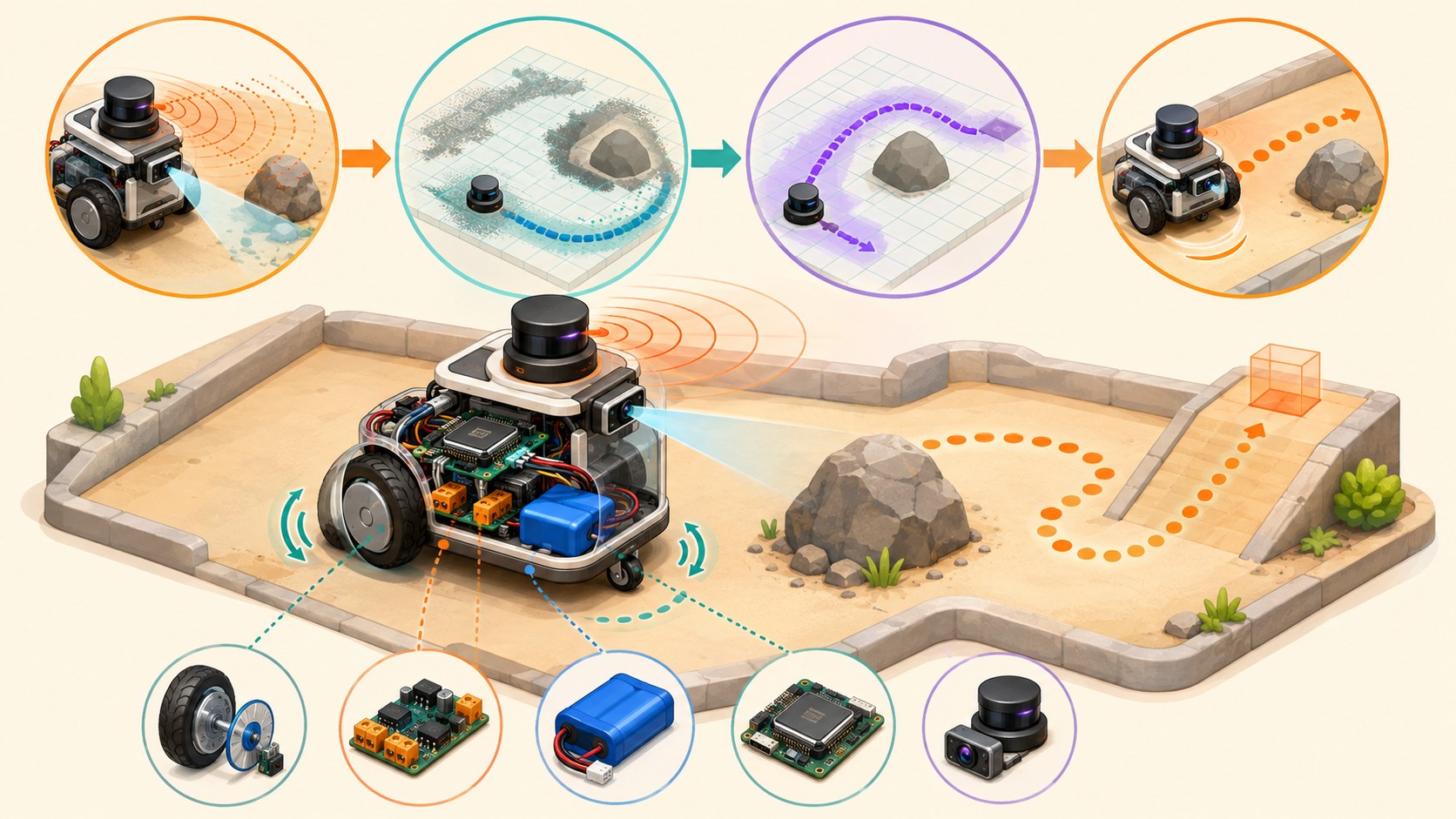
A ground robot reaches a goal by turning wheel motion and sensor readings into an estimated position, a safe path and continuous steering corrections.

ROSLiDAROdometry 4 guided sessions 8 skill tracks 3 example projects
Three-dimensional educational ground rover using wheel encoders, lidar and a camera to map and avoid an obstacle
Concept overview · generated for this Academy4Tech lesson
Start here

See the system, then build it.

A route that works on a clean floor may fail on dust, grass or a ramp. Mobile robotics is the science of measuring and managing that uncertainty.

01Compare differential and steering-based mobile robot motion
02Explain why wheel odometry drifts and how localization corrects it
03Trace a navigation loop through mapping, planning and control
04Design terrain and recovery tests with measurable results
Your progress Keep your learning momentum going

0 of 4 sessions complete

Interactive 3D learning studio

Mobile-robot navigation studio

Connect traction, wheel motion, localization, planning and recovery on a differential-drive rover.

Interactive system model · loads on request Poster mode
Explore the system in 3D Inspect the labelled subsystems and watch their modelled process. The lesson flow beside it is a separate conceptual sequence unless it explicitly names the same subsystem. The poster remains available if WebGL is unsupported.
Selected lesson · conceptual flow

Chassis, traction and steering

How do wheel speeds decide where a robot goes?

Step 1 of 4 · Wheel commands

Step through this lesson’s conceptual sequence here. Inspect the separate 3D subsystem model below it to understand the system’s structure.

3D subsystem inspector · 4 model parts
Mini experiment

Change one variable. Predict first, then test.

Keep the right-minus-left difference between −20% and +20% for a gentle path.

12%
Live result Move the control to test your prediction

Keep the right-minus-left difference between −20% and +20% for a gentle path.

Every highlighted 3D group corresponds to a labelled system part. A slider changes the model only when that relationship can be represented faithfully; otherwise the geometry stays still and the live calculation explains the effect. The model simplifies scale and geometry, so use the lesson’s safety notes, measurements and official documentation when building a real system.

01
Session 1 · 20 min

Chassis, traction and steering

How do wheel speeds decide where a robot goes?

Understand it

A differential-drive robot controls a left and right driven wheel independently. Equal speeds produce a straight path, different speeds produce a curve, and opposite speeds can rotate the chassis near its centre. Wheel diameter, track width, mass distribution, tyre grip and caster placement all affect the real motion.

Interactive concept flow

Step 1 of 4 Wheel commands

Choose a step to inspect it, or run the complete sequence.

Sequence progress
1 / 4
Picture it

A useful analogy

A person paddling a canoe turns by changing the effort on the two sides.

Apply it

Worked example

If the right wheel travels farther than the left wheel during the same time, the rover curves left. On loose sand, slip makes the real curve different from the calculation.

Try it
  1. Use two coins as left and right wheels.
  2. Move them equal distances, then move one farther.
  3. Sketch the expected path and one reason the real path could differ.
Quick checkWhat happens when ideal differential-drive wheels rotate at equal speed in opposite directions?

Answer: The robot rotates approximately in place around a point between the wheels.

02
Session 2 · 25 min

Odometry and localization

How does a rover know where it is?

Understand it

Wheel encoders estimate how far each wheel turns. Odometry adds those small motions to update position and heading, but every slip or size error accumulates. Localization compares odometry with other evidence such as an IMU, lidar map, camera landmarks or GNSS. The result is a pose estimate with uncertainty, not perfect truth.

Interactive concept flow

Step 1 of 4 Encoder motion

Choose a step to inspect it, or run the complete sequence.

Sequence progress
1 / 4
Picture it

A useful analogy

Walking with your eyes closed, you can count steps, but small errors grow until a landmark helps you correct your position.

Apply it

Worked example

A wheel encoder predicts the rover moved 2 m, while a lidar scan best matches the map at 1.86 m. The localization system combines evidence rather than blindly trusting one source.

Try it
  1. Mark a start pose on squared paper.
  2. Apply three forward and turn commands.
  3. Add a small error to each move and compare final predicted and true positions.
Quick checkWhy does wheel odometry usually drift over a long route?

Answer: Small errors from slip, wheel size and measurement accumulate each time motion is added.

03
Session 3 · 25 min

Map, plan and control

How does a robot choose and follow a safe path?

Understand it

Sensors update an environmental representation such as an occupancy grid or costmap. A planner searches for a path from the estimated pose to the goal. A controller converts a nearby part of that path into velocity commands while reacting to local obstacles. Navigation software coordinates planning, control and recovery as a repeating loop.

Interactive concept flow

Step 1 of 4 Sense obstacles

Choose a step to inspect it, or run the complete sequence.

Sequence progress
1 / 4
Picture it

A useful analogy

A route planner suggests streets, while the driver still steers around a temporary cone and checks where the car actually is.

Apply it

Worked example

A global path goes around a shelf. When a box appears, the local controller slows and steers around it, or stops and requests a new plan if no safe gap remains.

Try it
  1. Shade blocked cells on a paper grid.
  2. Draw a short safe path with clearance.
  3. Add a new obstacle and decide whether to steer locally, replan or stop.
Quick checkWhat is the difference between a planner and a controller?

Answer: The planner chooses a route toward the goal; the controller produces immediate motion commands to follow it safely.

04
Session 4 · 30 min

Terrain, recovery and evidence

What makes a rover reliable outside a perfect laboratory?

Understand it

Real terrain changes traction, clearance, vibration and sensor visibility. Engineers define operating limits, test surfaces and slopes one at a time, then record pose error, completion time, current and recovery events. Recovery behaviour might stop, reverse, rotate for a better view, replan or ask a human for help.

Interactive concept flow

Step 1 of 4 Define terrain

Choose a step to inspect it, or run the complete sequence.

Sequence progress
1 / 4
Picture it

A useful analogy

Hiking shoes, route choice and pace all change when a smooth pavement becomes a rocky hill.

Apply it

Worked example

A delivery rover must cross tile and carpet, climb a 7° ramp and stop 25 cm before an unexpected obstacle in at least 9 of 10 trials.

Try it
  1. Choose three test surfaces and one slope.
  2. Write a pass condition for obstacle stopping and route completion.
  3. Create a recovery decision for wheel slip and a blocked path.
Quick checkWhy should terrain tests change one condition at a time?

Answer: It makes the cause of a success or failure easier to identify and compare.

Beyond the guided sessions

Explore the whole Unmanned Ground Vehicles field

The guided sessions teach the foundations. This map widens the view across 8 important tracks, with explanations, practice prompts, knowledge checks, and official sources for deeper study.

Design and validate wheeled mobile robots from mechanics and odometry through perception, autonomy, cybersecurity, capability tests, and safeguarded operation.

Field map 0 of 8 tracks explored
Open a track to add it to your journey.
  1. Foundation Mobility hardware and energy
    Track overview

    A mobile base succeeds only when wheel arrangement, traction, gearing, structure, power, and braking suit the surface, payload, duty cycle, and stopping need.

    Core concepts

    Four ideas to understand

    1. Drive configurations

      Differential, skid-steer, Ackermann, omnidirectional, and tracked bases have different controllability and slip. Choose by terrain, maneuvering space, efficiency, and model complexity.

    2. Torque, speed, and gearing

      Wheel force depends on motor torque, gear ratio, radius, and losses, while maximum speed depends on motor speed and gearing. Include slope, acceleration, and rolling resistance margins.

    3. Traction and load transfer

      Available force is limited by tire-surface grip and normal load. Acceleration, turning, slopes, and payload position redistribute load and can cause slip or tip risk.

    4. Power and stopping hardware

      Motors draw peak current during startup, stall, and braking, and regenerated energy can raise bus voltage. Size conductors, protection, battery, and a risk-assessed stop architecture together; a safe stop may require controlled deceleration or holding before torque-off and energy isolation.

    Check your thinking Why can adding gear reduction improve climbing but reduce top speed?
    Answer

    Reduction multiplies wheel torque while lowering wheel rotational speed for a given motor speed.

  2. Applied Kinematics, odometry, and low-level control
    Track overview

    A robot converts body motion commands into wheel motion and estimates its movement back from sensors, while feedback limits error and detects loss of control.

    Core concepts

    Four ideas to understand

    1. Forward and inverse kinematics

      Forward kinematics estimates body motion from wheel motion; inverse kinematics computes wheel commands from desired body velocity. The equations depend on drive geometry and no-slip assumptions.

    2. Encoder odometry

      Wheel increments integrate into pose, but scale error and slip accumulate as drift. Calibrate wheel radius and separation using repeatable paths and independent references.

    3. Velocity feedback and limits

      Closed-loop control compares commanded and measured wheel speed. Acceleration, jerk, velocity, and command-timeout limits prevent abrupt or stale motion demands.

    4. Uncertainty and slip detection

      Odometry covariance should grow with uncertain motion rather than claiming perfect pose. Compare encoders with inertial or external evidence to detect slip and abnormal response.

    Check your thinking Why does encoder odometry drift even with high-resolution encoders?
    Answer

    Small scale errors and unmeasured wheel slip accumulate each time motion is integrated into pose.

  3. Applied Robot model and system bring-up
    Track overview

    Navigation software needs a coherent description of geometry, transforms, sensors, odometry, footprint, and lifecycle before higher-level autonomy can be trusted.

    Core concepts

    Four ideas to understand

    1. URDF and transform tree

      The model connects base, wheels, sensors, and other links through named frames. A wrong transform makes valid sensor readings appear in the wrong place.

    2. Driver and control interfaces

      Drivers translate encoders, motor commands, battery state, and faults into stable interfaces. Units, signs, limits, update rate, timeout, and fault semantics must be documented.

    3. Footprint and collision envelope

      A footprint approximates the base for planning, while a safety envelope may need extra space for braking, localization error, loads, or moving parts. Both must represent the current configuration.

    4. Lifecycle and health startup

      Bring up power, drivers, transforms, localization, maps, planners, and controllers in a checked sequence. Do not activate motion until required health conditions are present.

    Check your thinking What visible navigation symptom can a wrong lidar transform create?
    Answer

    Obstacles can appear shifted or rotate incorrectly relative to the robot, corrupting mapping and collision avoidance.

  4. Applied Perception, mapping, and localization
    Track overview

    Mobile robots turn range, vision, inertial, and odometry evidence into environmental representations and a pose estimate with explicit uncertainty.

    Core concepts

    Four ideas to understand

    1. Range and vision observations

      Lidar, sonar, depth, and cameras differ in field of view, surface response, lighting sensitivity, resolution, and blind zones. Mounting and timestamp quality are part of the observation.

    2. Occupancy and costmaps

      An occupancy map represents where space appears free or occupied; costmaps add inflated, dynamic, keepout, or speed-related costs for planning. They are estimates, not certified barriers.

    3. SLAM and map quality

      SLAM estimates trajectory and map together using motion and repeated observations. Poor geometry, moving scenes, wheel slip, or bad loop closure can distort the result.

    4. Localization and relocalization

      Localization compares current observations with a prior map and maintains a pose distribution. The robot needs defined behavior when confidence drops or the map is no longer valid.

    Check your thinking Why is a costmap not the same as a raw sensor scan?
    Answer

    It combines observations with map layers, clearing rules, inflation, and policy costs for planning over time.

  5. Advanced Planning, tracking, and recovery
    Track overview

    Navigation selects feasible routes, turns them into bounded commands, monitors progress, and executes recovery when the environment or robot violates assumptions.

    Core concepts

    Four ideas to understand

    1. Global path planning

      A global planner searches a representation of traversable space from start to goal. Its route quality depends on map accuracy, footprint, cost policy, and kinematic constraints.

    2. Local control and smoothing

      A controller tracks the path while reacting to nearby obstacles and motion limits. Smoothing and feasible-trajectory checks prevent commands the base cannot follow.

    3. Behavior trees and task logic

      A behavior tree coordinates planning, control, checks, and recovery while exposing decision flow. Recovery should address a diagnosed condition rather than repeat forever.

    4. Progress and collision monitoring

      Independent progress, speed, and proximity checks can slow or stop motion when a controller stalls or an obstacle enters a critical zone. They add defense but do not replace safety-rated functions.

    Check your thinking Why should a recovery action have an exit condition and attempt limit?
    Answer

    Without them, the robot may repeat ineffective or hazardous motion instead of stopping or requesting help.

  6. Advanced Task autonomy, docking, and human interaction
    Track overview

    Useful robots combine navigation with mission state, docking, payload actions, fleet coordination, and clear human control and status.

    Core concepts

    Four ideas to understand

    1. Mission and payload state machines

      Separate navigation goals from task states such as load, inspect, deliver, wait, and recover. Define retries, idempotent actions, and what happens after interruption.

    2. Docking and energy management

      Docking needs approach sensing, alignment, contact confirmation, charging interlocks, and escape behavior. Energy policy should reserve enough capacity to reach a safe or charge location.

    3. Fleet and traffic coordination

      Multiple robots need shared rules for routes, priority, blocked areas, and deadlock. A fleet service should not remove each robot's local collision response.

    4. Human interface and manual recovery

      People need understandable state, intent, warnings, stop controls, and recovery instructions. Manual control must have explicit authority, speed limits, and communication-loss behavior.

    Check your thinking What makes a mission action idempotent?
    Answer

    Repeating it after uncertainty has the same safe intended effect instead of duplicating an irreversible action.

  7. Advanced Capability testing, maintenance, and cybersecurity
    Track overview

    Repeatable capability tests, configuration evidence, preventive maintenance, and protected interfaces are needed to keep performance trustworthy after deployment.

    Core concepts

    Four ideas to understand

    1. Capability-based test design

      Test navigation, localization, docking, obstacle response, communication loss, and other claimed capabilities in representative conditions. Record the operational envelope and uncertainty instead of one best run.

    2. Logs and configuration baselines

      Tie maps, calibration, software, parameters, payload, test course, and results to a versioned configuration. This lets a change be compared with the last accepted baseline.

    3. Inspection and predictive evidence

      Wheels, bearings, brakes, cables, batteries, and sensors wear or shift. Scheduled checks plus trends in current, temperature, vibration, and error can reveal degradation early.

    4. Device cybersecurity

      Manage device identity, access, data protection, configuration, updates, and cybersecurity state. Segment networks and ensure loss of a cloud or fleet service leaves a safe local response.

    Check your thinking Why must test results include the robot configuration and environment?
    Answer

    Capability can change with software, parameters, payload, floor, lighting, traffic, and other conditions, so results without context are not reproducible.

  8. Advanced Safety engineering and regulated deployment
    Track overview

    A mobile robot operating near people needs formal hazard analysis, protective functions, validated stopping behavior, site controls, and standards matched to its application. ISO 3691-4 applies to driverless industrial trucks and their systems, not automatically to every outdoor, research, service, or consumer robot.

    Core concepts

    Four ideas to understand

    1. Hazards and operating zones

      Identify crushing, impact, trapping, tip, load, energy, fire, and unexpected-start hazards for every mode. Define operating, restricted, transfer, and maintenance zones from the real site.

    2. Safety functions and independence

      Emergency stop, protective stop, speed limiting, presence sensing, braking, and restart interlocks need required integrity and validation. General navigation sensors or software may not be safety-rated.

    3. Stopping and verification

      Stopping distance varies with speed, load, floor, slope, brake condition, latency, and tire grip. Measure worst credible cases and set protective distances with margin.

    4. Commissioning and change review

      Qualified people must validate the integrated robot, site, traffic rules, interfaces, foreseeable misuse, and emergency procedures. Changes to payload, map, speed, software, or layout require impact review.

    Check your thinking Why can a navigation lidar not automatically be treated as a protective safety scanner?
    Answer

    Its hardware, diagnostics, software path, coverage, and integrity may not meet the required safety function or validated performance level.

Verified next steps

Official references

Use these primary sources to extend the explanations and check current guidance.

  1. ros2_control Project diff_drive_controller
  2. Navigation2 Project First-Time Robot Setup Guide
  3. Navigation2 Project Navigation Concepts
  4. ASTM International ASTM F3470-20 — Standard Guide for A-UGV Capabilities
  5. International Organization for Standardization ISO 3691-4:2023 — Industrial trucks — Safety requirements and verification — Part 4: Driverless industrial trucks and their systems
  6. National Institute of Standards and Technology IoT Device Cybersecurity Capability Core Baseline
Three-project build pathway

Learn Unmanned Ground Vehicles by making it work.

Start small, combine the ideas, then complete a measured challenge. Every project includes a material list, four build milestones, evidence to collect, and a safe next step.

  1. Starter · 3–5 hours Calibrate a differential-drive twin Learn one dependable building block Model a two-wheel robot in simulation, convert commanded body motion into wheel motion, and use straight, rotate, and arc tests to expose wheel-radius and wheel-separation errors.
    What you will learn

    Learning goals

    • Relate linear and angular body velocity to left and right wheel speed.
    • Explain how encoder scale, wheel radius, track width, slip, and sign conventions affect odometry.
    • Use controlled trajectories to calibrate parameters from evidence.
    Prepare

    Materials and tools

    • A differential-drive simulator or ros2_control-compatible virtual base
    • Command, odometry, and pose logging tools
    • A calculation sheet and a marked virtual test course
    Build sequence

    Four milestones

    1. Draw the base frame and wheel geometry, derive three command cases, and declare velocity and acceleration limits.

    2. Configure the simulated controller and verify command timeout, wheel direction, odometry frames, and stopped initial state.

    3. Run forward, in-place rotation, and constant-radius arc trials with intentionally perturbed wheel parameters.

    4. Estimate corrected parameters, repeat all trials, and compare position, heading, and path-shape errors before and after calibration.

    Prove it works

    Evidence to collect

    • Calculated wheel commands agree with logged wheel velocities for straight, rotate, and arc cases using consistent units and signs.
    • Before/after plots show how each corrected parameter changes distance, heading, or curvature error.
    • The controller reaches zero command after timeout and respects the declared virtual speed and acceleration bounds.
  2. Builder · 7–10 hours Navigate a simulated delivery course Connect multiple ideas into a working system Configure a virtual mobile robot to localize, plan, track, and recover through a delivery route while measuring clearance, localization consistency, and completion behavior.
    What you will learn

    Learning goals

    • Connect frames, odometry, range sensing, map, localization, planner, controller, and behavior-tree responsibilities.
    • Choose footprint, inflation, speed, goal, and progress settings from robot and environment constraints.
    • Diagnose failures from costmaps, transforms, localization, plans, commands, and recovery events.
    Prepare

    Materials and tools

    • ROS 2, Nav2, and a supported differential-drive simulation environment
    • A small mapped course with narrow passage, static obstacle, open area, and three delivery poses
    • Visualization, bag/log recording, and metric-analysis tools
    Build sequence

    Four milestones

    1. Validate robot footprint, frames, sensors, odometry, map scale, localization startup, and conservative motion limits before enabling autonomy.

    2. Configure a baseline route and record path length, completion time, minimum simulated clearance, pose error, and recovery count.

    3. Tune one parameter family at a time, rerun identical starts, and reject changes that improve speed by violating clearance or stability limits.

    4. Test blocked corridor, displaced start, localization disturbance, and unreachable goal; document safe stop, recovery, or refusal behavior.

    Prove it works

    Evidence to collect

    • Three repeat runs reach all valid delivery poses within stated pose, clearance, time, and recovery limits.
    • A controlled comparison attributes each accepted tuning change to measured improvement without silently changing the course or start state.
    • Failure trials provide synchronized costmap, localization, plan, command, and event evidence supporting the diagnosis.
  3. Challenge · 10–15 hours Assure a warehouse mission in simulation Test, measure, and improve a complete solution Build a simulation-stage capability and safety case for a fleet-style transport mission using bounded zones, docking, task states, degraded modes, cybersecurity controls, maintenance evidence, and repeatable tests.
    What you will learn

    Learning goals

    • Translate mission and environment risks into capability tests, operational limits, diagnostics, and stop conditions.
    • Coordinate navigation, docking, task state, human interaction, recovery, and device-security responsibilities.
    • Distinguish software test evidence from the additional validation required for an industrial mobile robot deployment.
    Prepare

    Materials and tools

    • ROS 2/Nav2 simulation with a warehouse-style map and one virtual robot
    • Virtual docking station, keep-out/slow zones, dynamic-obstacle scenarios, and task coordinator
    • Versioned configurations, logs, seeded test scenarios, threat model, and assurance-report template
    Build sequence

    Four milestones

    1. Define transport tasks, operating zones, payload assumptions, speed limits, stop conditions, human handoff, metrics, and a hazard/threat register.

    2. Implement mission states for dispatch, travel, docking, load wait, return, degraded mode, and operator-required recovery with explicit timeouts.

    3. Run seeded trials for obstruction, localization loss, docking failure, stale task, network interruption, unauthorized command, and low-energy condition.

    4. Summarize completion, clearance, stop, recovery, diagnostic, and security evidence in a capability matrix and simulation-stage release decision.

    Prove it works

    Evidence to collect

    • Repeated nominal missions meet declared completion, containment, clearance, docking, and timing metrics across all approved zones.
    • Each injected hazard or threat leads to the predeclared bounded stop, rejection, recovery, or operator-required state with traceable logs.
    • The assurance report identifies residual risks and clearly lists physical tests, safety-rated controls, standards work, and cybersecurity lifecycle tasks still required.
Words to know

Build your vocabulary.

Differential drive
Steering produced by controlling left and right wheel speeds independently.
Encoder
A sensor that measures rotation or incremental movement.
Odometry
An estimate of motion calculated from movement measurements over time.
Pose
A robot’s estimated position and orientation.
Costmap
A grid representation that assigns travel cost to free, risky and occupied space.
Recovery
A behaviour used when normal navigation cannot continue.
Work safely

Before you power or move anything.

  • Test at low speed in a bounded area with a reachable emergency stop.
  • Keep hands, hair and loose clothing away from wheels and drive parts.
  • Use a suitable motor driver, fuse or current limit and secured battery.
  • Do not test autonomous vehicles near roads, stairs or members of the public.
Keep studying

Official documentation.

These lessons simplify the first ideas. Use the original documentation when building, checking details or moving to the next level.

Continue learning

Related Academy4Tech content.

ProjectAdvanced

WildeBeest Pro

A complete dual-ROS autonomous-robot reference stack joining CAD, simulation, navigation, sensor fusion, a safety-oriented Arduino controller and an operator dashboard.

ROS 2 JazzyPythonC++Arduino

Learn by building.

Choose a real project, identify the smallest subsystem you can test, and document what the measurement tells you.