
Intermediate · visual course

RoboDK

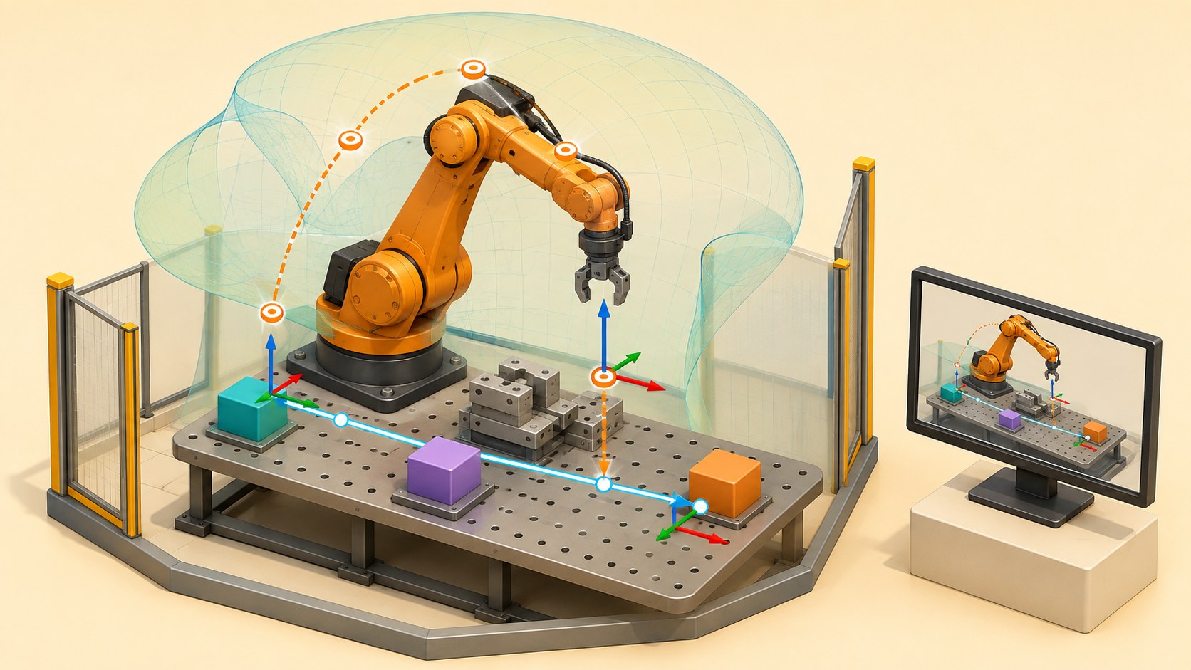
RoboDK creates a digital robot station where frames, tools, targets and motion can be tested before controller-specific code is generated.

RoboDKSimulationRobot arms 4 guided sessions 8 skill tracks 3 example projects
Three-dimensional RoboDK learning scene with an industrial robot, reference frames, target poses and collision-free simulated paths
Concept overview · generated for this Academy4Tech lesson
Start here

See the system, then build it.

A simulation is a powerful engineering model, not a safety guarantee. The virtual station must match the real cell and real validation still matters.

01Organize a RoboDK station using robots, objects, tools and reference frames
02Explain joint and Cartesian targets plus joint and linear motion
03Check reach, singularity risk, collisions and cycle sequence in simulation
04Describe the offline-programming path from station to verified robot program
Your progress Keep your learning momentum going

0 of 4 sessions complete

Interactive 3D learning studio

Robot-cell simulation studio

Inspect frames, targets, motion, reach and collision risk before validating on a real robot.

Interactive system model · loads on request Poster mode
Explore the system in 3D Inspect the labelled subsystems and watch their modelled process. The lesson flow beside it is a separate conceptual sequence unless it explicitly names the same subsystem. The poster remains available if WebGL is unsupported.
Selected lesson · conceptual flow

Build a station with frames

How does the simulator know where every item belongs?

Step 1 of 4 · Robot base

Step through this lesson’s conceptual sequence here. Inspect the separate 3D subsystem model below it to understand the system’s structure.

3D subsystem inspector · 4 model parts
Mini experiment

Change one variable. Predict first, then test.

Choose a 10–35 mm blend for the sample path.

20 mm
Live result Move the control to test your prediction

Choose a 10–35 mm blend for the sample path.

Every highlighted 3D group corresponds to a labelled system part. A slider changes the model only when that relationship can be represented faithfully; otherwise the geometry stays still and the live calculation explains the effect. The model simplifies scale and geometry, so use the lesson’s safety notes, measurements and official documentation when building a real system.

01
Session 1 · 20 min

Build a station with frames

How does the simulator know where every item belongs?

Understand it

A RoboDK station stores robots, objects, tools, reference frames, targets and programs. A reference frame describes position and orientation relative to a parent frame. The tool centre point describes the working point of the gripper or process tool. A clear frame hierarchy lets a whole fixture and its targets move together when its measured location changes.

Interactive concept flow

Step 1 of 4 Robot base

Choose a step to inspect it, or run the complete sequence.

Sequence progress
1 / 4
Picture it

A useful analogy

A street address locates a building in a city, while a room number locates an object inside that building.

Apply it

Worked example

Attach a part and its pick targets to a table frame. If the table frame moves 50 mm, the part and targets keep their correct relationship to the table.

Try it
  1. Sketch a station tree for a robot, table, part and gripper.
  2. Draw local axes for the robot base and table.
  3. Predict which items move when the table frame changes.
Quick checkWhy attach targets to a work reference frame?

Answer: The targets keep their relationship to the workpiece and can be updated together when that frame is remeasured or moved.

02
Session 2 · 25 min

Targets and motion types

What exactly does a robot target remember?

Understand it

A Cartesian target records the tool pose relative to a reference frame; a joint target records robot joint values. A joint move usually chooses an efficient coordinated path in joint space, while a linear move keeps the tool centre point on a straight line in Cartesian space. The right choice depends on approach, process and clearance needs.

Interactive concept flow

Step 1 of 4 Choose frame and tool

Choose a step to inspect it, or run the complete sequence.

Sequence progress
1 / 4
Picture it

A useful analogy

Your hand can move directly across a table, or your shoulder and elbow can take a comfortable route that makes the hand follow a curve.

Apply it

Worked example

Use a joint move from home to an approach target, then a slower linear move down to a pick target so the gripper approaches the part predictably.

Try it
  1. Place home, approach, pick and retreat points on a workcell sketch.
  2. Choose joint or linear motion for each connection.
  3. Explain where speed should be reduced.
Quick checkWhen is a linear move especially useful?

Answer: When the tool must follow a predictable straight path, such as approaching a part or following a process line.

03
Session 3 · 25 min

Reach, collisions and calibration

Why can a visually correct target still fail?

Understand it

A target may be outside reach, near a joint limit, in a singular configuration or reachable only through an obstacle. Collision checks need relevant station geometry, and accurate offline programming needs calibrated tool and reference frames. Simulate the complete sequence, inspect robot configurations and allow real clearance instead of accepting a single successful pose.

Interactive concept flow

Step 1 of 4 Check reach

Choose a step to inspect it, or run the complete sequence.

Sequence progress
1 / 4
Picture it

A useful analogy

You may touch a shelf point while standing still, yet your elbow can hit a wall during the movement toward it.

Apply it

Worked example

The gripper reaches a box, but the elbow clips the fixture on the approach. Moving the approach target and choosing another robot configuration creates a clear path.

Try it
  1. Mark possible collision pairs in a sample cell.
  2. Draw a safer approach and retreat path.
  3. List tool and frame measurements that must match the real setup.
Quick checkDoes a collision-free target prove the whole movement is collision-free?

Answer: No. Every path segment and relevant moving geometry must be checked throughout the motion.

04
Session 4 · 30 min

Offline program to real validation

How does a simulation become controller-ready code?

Understand it

Offline programming builds and tests a robot sequence away from production. RoboDK uses a post processor to translate generic simulated instructions into the selected controller’s program format. Before production, engineers review generated code, confirm frames and tools, transfer through an approved method, then validate at reduced speed under the robot maker’s safety procedure.

Interactive concept flow

Step 1 of 4 Validate station

Choose a step to inspect it, or run the complete sequence.

Sequence progress
1 / 4
Picture it

A useful analogy

A translator can convert a carefully written route into another language, but a qualified driver still checks the real road before carrying passengers.

Apply it

Worked example

Simulate a pick-and-place cycle, check targets and collisions, select the correct robot post processor, generate the program, then perform supervised low-speed validation in the real cell.

Try it
  1. Write a pick-and-place program sequence.
  2. Create a pre-export checklist for robot, tool, frames and post processor.
  3. Add a reduced-speed real-cell validation plan with stop conditions.
Quick checkWhat does a post processor do?

Answer: It converts the generic offline program into syntax and structure for a specific robot controller.

Beyond the guided sessions

Explore the whole RoboDK field

The guided sessions teach the foundations. This map widens the view across 8 important tracks, with explanations, practice prompts, knowledge checks, and official sources for deeper study.

Create a traceable industrial-robot digital twin, program and verify motion, then transfer it through controlled, standards-aware commissioning.

Field map 0 of 8 tracks explored
Open a track to add it to your journey.
  1. Foundation Stations and digital-twin structure
    Track overview

    A RoboDK station stores robots, tools, frames, objects, targets, programs, and settings in a hierarchy that should mirror the real cell's dependencies.

    Core concepts

    Four ideas to understand

    1. Station tree and item types

      The tree expresses ownership and reference relationships, not just display order. Clear names and grouping make hidden dependencies and active items easier to audit.

    2. Robot model selection

      Choose the exact mechanism, controller family, reach, payload, and axes where possible. A similar-looking model can have different kinematics, limits, or postprocessor needs.

    3. CAD, fixtures, and collision geometry

      Imported STEP, IGES, STL, or other geometry establishes the virtual workspace. Simplify safely for performance while retaining surfaces and volumes that matter to reach and collision.

    4. Configuration baseline

      The station file, geometry revisions, robot/controller identity, tools, calibration, and options form a baseline. Version them together so a result can be reproduced.

    Check your thinking Why should the station tree mirror real reference dependencies?
    Answer

    Moving or updating a parent frame then moves its dependent items consistently and makes the cell relationship auditable.

  2. Foundation Reference frames, TCPs, and calibration
    Track overview

    Robot motion is meaningful only when base, work, tool, and measurement coordinate systems agree with the real installation.

    Core concepts

    Four ideas to understand

    1. Frame transformations

      A frame defines position and orientation relative to another frame, forming a transformation chain. Editing the wrong parent can move every dependent target unexpectedly.

    2. Tool center point

      The TCP is the controlled point and orientation on the tool. Geometry placement and the calibrated TCP are related but are not automatically the same.

    3. Work-object registration

      A work frame connects CAD and targets to a physical fixture or part. Registering the frame is safer and more maintainable than touching up every target after the fixture moves.

    4. Calibration and validation

      Calibration estimates model corrections from reference measurements; validation checks independent points afterward. Measurement quality and setup determine whether simulated accuracy transfers to reality.

    Check your thinking Why is changing a work frame usually better than retouching every target after a fixture shifts?
    Answer

    Targets referenced to that frame update consistently, preserving their geometry and reducing independent editing errors.

  3. Applied Targets, instructions, and motion types
    Track overview

    Programs combine joint or Cartesian targets with motion and process instructions; each representation creates different path, posture, and feasibility behavior.

    Core concepts

    Four ideas to understand

    1. Joint and Cartesian targets

      A joint target fixes axis values, while a Cartesian target specifies a tool pose and may allow several robot configurations. Use the representation that protects the intended constraint.

    2. MoveJ, MoveL, and circular motion

      Joint motion generally finds an efficient axis-space path; linear motion constrains the TCP to a line; circular motion follows an arc. A linear path can fail even when both endpoints are reachable.

    3. Approach, process, and retreat

      Separate safe approach and retreat from the process segment so speeds, orientation, and collision checks match each phase. Define a recovery pose and a risk-assessed controlled path to it; never assume that motion to the pose is safe.

    4. Speed, acceleration, blending, and I/O

      Motion settings and blending trade time against path accuracy and stopping behavior, while I/O coordinates tool actions. Exact stops may be required before contact, release, or process interlocks; safety functions require safety-rated controller paths, not ordinary program I/O.

    Check your thinking Why can a MoveL fail between two individually reachable targets?
    Answer

    Every pose along the straight Cartesian path must be reachable with a valid configuration and within joint and singularity limits.

  4. Advanced Reachability, configuration, and singularities
    Track overview

    A reachable pose may still force an unsuitable posture, cross a singularity, exceed an axis limit, or leave too little margin for the real cell.

    Core concepts

    Four ideas to understand

    1. Workspace and reach margin

      Nominal reach describes a boundary, not a robust working region. Tool length, orientation, payload, obstacles, and calibration error reduce usable reach.

    2. Robot configurations

      Many Cartesian poses have elbow, shoulder, or wrist alternatives. Lock or guide configuration so a program does not unexpectedly flip posture between nearby targets.

    3. Joint limits and external axes

      Axis position, speed, and acceleration limits constrain the full path, and external axes add coordination choices. Keep distance from hard limits to tolerate model and process variation.

    4. Singularities

      At a singularity, some Cartesian motions require very large or indeterminate joint motion. Reorient the tool, change posture or path, or reposition the cell rather than forcing the move.

    Check your thinking What is dangerous about commanding Cartesian motion near a singularity?
    Answer

    A small TCP demand can require very high or unpredictable joint motion, causing faults or hazardous movement.

  5. Applied Collision, clearance, and cycle review
    Track overview

    Virtual collision and timing analysis reveal many path and layout problems, but only when geometry, collision pairs, sampling, margins, and controller behavior are realistic.

    Core concepts

    Four ideas to understand

    1. Collision pairs and map

      Define which robot, tool, part, fixture, and cell objects need checking. Omitting a pair can make a colliding program appear clean, while excessive pairs slow analysis.

    2. Path sampling and continuous risk

      Endpoint checks miss collisions between targets, and coarse sampling can step over thin geometry. Choose path checks and step sizes suitable for speed, shape, and clearance.

    3. Clearance and model uncertainty

      A collision-free mathematical boundary has no physical margin. Inflate or offset geometry to cover calibration, flex, tooling, part, fixturing, and stopping variation.

    4. Cycle-time interpretation

      Simulated time depends on speed, acceleration, blending, I/O waits, controller motion model, and process assumptions. Validate critical estimates against the real controller and operation.

    Check your thinking Why is zero collision in simulation not proof of safe real clearance?
    Answer

    Geometry, calibration, flex, fixtures, parts, sampling, and controller motion can differ from the model.

  6. Applied Process paths and CAD-to-robot workflows
    Track overview

    Manufacturing simulations must convert geometry into tool poses, process parameters, transitions, and quality checkpoints that the chosen robot can actually execute.

    Core concepts

    Four ideas to understand

    1. Curve and point import

      CAD curves, points, and surface normals can seed a path, but their coordinate system, order, density, and orientation need verification. Raw geometry is not yet a robot process.

    2. Tool orientation and process frame

      Tool angle, standoff, lead, work frame, and direction affect both quality and reachability. Permit only orientation freedom that the real process can tolerate.

    3. Path optimization and transitions

      Point spacing, approach order, retracts, joins, and posture choices influence cycle time and feasibility. Optimization must preserve process and safety constraints.

    4. Process validation checkpoints

      Verify tool state, part state, path coverage, speed, orientation, and event timing at defined checkpoints. Simulation should expose deviations rather than merely animate motion.

    Check your thinking Why can a valid CAD curve still produce an invalid robot process?
    Answer

    It may have the wrong frame, point order, orientation, density, reach, collision clearance, speed, or process transitions.

  7. Advanced Offline programming, postprocessors, and automation
    Track overview

    Offline programming transfers verified intent to a specific controller, so postprocessor output, controller settings, versioning, and automated station changes all need review.

    Core concepts

    Four ideas to understand

    1. Program generation

      RoboDK resolves station instructions into robot-program intent. Generated output must correspond to the selected robot, active frames, tool, configuration, and process settings.

    2. Postprocessors and controller dialects

      A postprocessor translates generic instructions into a manufacturer and controller-specific language. Review motion, frame, tool, I/O, units, speed, and unsupported-feature handling.

    3. API and repeatable automation

      The API can create, inspect, and generate station content reproducibly. Scripts need validated inputs, error checks, deterministic names, and version control because they can multiply mistakes quickly.

    4. Diff, review, and release

      Compare generated code and station metadata with the approved baseline, then archive the exact output sent to the controller. Regenerate after any relevant model or configuration change.

    Check your thinking Why must generated controller code still be reviewed?
    Answer

    Translation settings, unsupported instructions, units, frames, I/O, versions, or controller behavior can differ from the simulated intent.

  8. Advanced Commissioning, safety, and lifecycle validation
    Track overview

    Simulation supports engineering review but is not a safety-rated proof; qualified commissioning must validate the integrated real robot cell across every operating and maintenance mode.

    Core concepts

    Four ideas to understand

    1. Simulation-to-reality validation

      Confirm robot and controller versions, mastering, frames, TCP, payload, tools, fixtures, programs, and I/O against the physical cell. Independent validation points reveal model mismatch.

    2. Risk assessment and safeguarding

      The application risk assessment drives guards, interlocks, protective devices, safe distances, modes, stops, and procedures. A rendered safety zone does not implement a safety function.

    3. Reduced-risk proving

      Qualified personnel should first prove motion with controlled mode, reduced speed, clear area, ready stop, and stepwise expansion. Unexpected motion requires stopping and resolving the cause.

    4. Change and lifecycle control

      Installation, integration, commissioning, operation, maintenance, and decommissioning each introduce hazards. Changes to tooling, fixtures, speed, software, payload, or process require impact review and regression tests.

    Check your thinking Can a collision-free RoboDK station replace physical safeguarding validation?
    Answer

    No; simulation is not a safety-rated protective system and cannot prove all real geometry, behavior, failures, stopping, or human interaction.

Verified next steps

Official references

Use these primary sources to extend the explanations and check current guidance.

  1. RoboDK Getting Started
  2. RoboDK Robot Programs
  3. RoboDK Collision Detection
  4. RoboDK Robot Calibration (Laser Tracker)
  5. RoboDK Reference Frames
  6. RoboDK Define a Tool (TCP)
  7. International Organization for Standardization ISO 10218-2:2025 — Robotics — Safety requirements — Part 2: Industrial robot applications and robot cells
Three-project build pathway

Learn RoboDK by making it work.

Start small, combine the ideas, then complete a measured challenge. Every project includes a material list, four build milestones, evidence to collect, and a safe next step.

  1. Starter · 3–5 hours Build a framed pick-and-place twin Learn one dependable building block Create a simulation-only RoboDK station that uses named reference frames, a defined TCP, approach/retreat targets, and appropriate joint or linear moves for a simple pick-and-place cycle.
    What you will learn

    Learning goals

    • Explain how station, robot-base, object, target, and tool frames change pose meaning.
    • Define and verify a TCP instead of compensating with visually adjusted targets.
    • Choose joint and linear motion from process intent and inspect reachability and configuration.
    Prepare

    Materials and tools

    • RoboDK with one library robot, simple gripper geometry, table, source tray, and destination tray
    • Primitive low-polygon workpieces and a dimensioned virtual layout
    • A station checklist and screen-recording or screenshot tool; no live robot connection
    Build sequence

    Four milestones

    1. Build the station tree, name every item, place base/object frames from the layout, and document their parent relationships.

    2. Define the gripper TCP and verify its orientation and offset with a known pose and visible axes.

    3. Create home, approach, pick, retreat, transfer, place, and exit targets using joint moves for travel and linear moves where path shape matters.

    4. Simulate the cycle from three initial states, inspect target reachability/configuration, and add clear comments, speed zones, and reset instructions.

    Prove it works

    Evidence to collect

    • The station tree and frame screenshots match the dimensioned layout and contain no unnamed corrective offsets.
    • The TCP reaches pick and place features with the intended orientation, approach vector, and retract clearance.
    • Three repeat simulations complete in the same order with reachable targets and no visible table, tray, or workpiece collision.
  2. Builder · 6–9 hours Optimize a collision-aware palletizer Connect multiple ideas into a working system Create a simulated palletizing cell that generates a target grid, checks robot configurations and collisions, and improves cycle time without sacrificing declared clearance or process constraints.
    What you will learn

    Learning goals

    • Generate repeated targets relative to frames rather than copying world-coordinate poses.
    • Evaluate reachability, joint limits, robot configuration, singularity risk, collision pairs, and tool/workpiece clearance.
    • Optimize move type, approach geometry, speed, and blending against measured safety and quality constraints.
    Prepare

    Materials and tools

    • RoboDK with an industrial robot model, gripper, infeed, pallet, workpieces, floor, fence, and representative obstacles
    • A pallet pattern specification, part/tool dimensions, and declared virtual clearance limit
    • RoboDK collision checking and optional API scripting environment
    Build sequence

    Four milestones

    1. Define the station hierarchy, pallet frame, TCP, payload assumption, collision map, exclusion zones, target grid, and acceptance metrics.

    2. Generate approach/place/retreat targets for every pallet position while preserving intended orientation and stable robot configuration.

    3. Enable relevant collision pairs, inspect unreachable and near-singular cases, and modify layout or paths rather than hiding failed targets.

    4. Compare a conservative baseline with one optimized cycle, then rerun full-path collision, clearance, reachability, and process-order reviews.

    Prove it works

    Evidence to collect

    • Every pallet position has a traceable target result: accepted, deliberately reconfigured, or rejected with a recorded reason.
    • A full-cycle report shows no detected collision and documents minimum modeled clearance, joint-limit margin, and configuration changes.
    • The optimized cycle improves measured simulated time while preserving every declared path, approach, clearance, and sequence constraint.
  3. Challenge · 9–13 hours Release-review a CAD process path Test, measure, and improve a complete solution Turn a CAD curve into a simulation-validated process program and auditable offline-code package, including frames, TCP, reach/configuration, collision, process orientation, postprocessor identity, and commissioning limits.
    What you will learn

    Learning goals

    • Convert CAD geometry into process targets whose orientation, spacing, approach, speed, and blending express the manufacturing intent.
    • Separate nominal simulation, robot calibration, cell calibration, controller postprocessing, and real commissioning responsibilities.
    • Perform a release review that preserves traceability and explicitly identifies what simulation cannot prove.
    Prepare

    Materials and tools

    • RoboDK with a chosen robot, tool, fixture, representative cell geometry, and a benign CAD curve
    • A process specification for orientation, standoff/contact assumption, speed, path tolerance, approach, and exit
    • An offline postprocessor selected for study only, plus review and commissioning-checklist templates
    Build sequence

    Four milestones

    1. Build and dimension the station, define object/reference frames and TCP, document nominal calibration assumptions, and freeze input CAD revision.

    2. Generate the process path, inspect normals and point density, add approach/exit moves, and repair unreachable, singular, or configuration-flip regions.

    3. Run relevant collision pairs and clearance review for the complete path, then compare exact-stop and bounded-blend variants against process tolerance and cycle time.

    4. Generate offline code for review, record postprocessor/controller assumptions, and issue a release bundle with simulation evidence and a hold-point commissioning plan.

    Prove it works

    Evidence to collect

    • A path audit confirms target order, orientation, point spacing, approach/exit, reach, configuration continuity, and declared process tolerance.
    • Complete-cycle evidence records collision settings, clearance assumptions, joint behavior, cycle time, and every reviewed exception.
    • The offline-code package identifies source station/CAD revisions, robot/controller/postprocessor versions, frame/TCP assumptions, reviewer, and unresolved commissioning tests.
Words to know

Build your vocabulary.

Station
A RoboDK project containing the robot, geometry, frames, targets and programs.
Reference frame
A coordinate system that locates an item relative to another item.
TCP
The tool centre point used as the working position and orientation of a robot tool.
Target
A stored robot pose or set of joint values.
Singularity
A robot configuration where some motions become poorly conditioned or require extreme joint speed.
Post processor
Software that generates controller-specific robot code from offline instructions.
Work safely

Before you power or move anything.

  • Treat the simulation as a model, never as proof that a real cell is safe.
  • Only trained and authorized people should operate or validate an industrial robot.
  • Use guarding, approved stop systems and reduced-speed procedures required by the robot manufacturer and site.
  • Confirm the active tool, frames, payload and program before any real motion.
Keep studying

Official documentation.

These lessons simplify the first ideas. Use the original documentation when building, checking details or moving to the next level.

Continue learning

Related Academy4Tech content.

Learn by building.

Choose a real project, identify the smallest subsystem you can test, and document what the measurement tells you.