You can understand RoboDK without treating it as magic or memorizing a long list of terms. Start with one simple mental model, connect each part to an everyday example, and then add the technical details that make the system dependable.
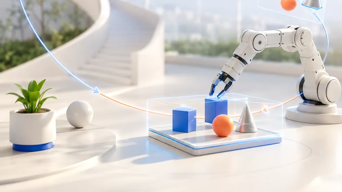
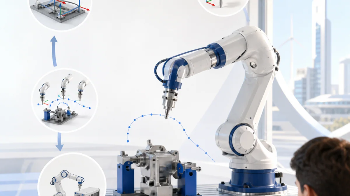
The big idea: RoboDK creates a digital robot station where frames, tools, targets and motion can be tested before controller-specific code is generated.
A simulation is a powerful engineering model, not a safety guarantee. The virtual station must match the real cell and real validation still matters.
Why this matters
Robot simulation lets an engineer test reach, motion and collisions before occupying a real machine. The simulation becomes valuable when its frames, tools and calibration match the physical cell.
By the end of this guide, you will be able to:
- Organize a RoboDK station using robots, objects, tools and reference frames
- Explain joint and Cartesian targets plus joint and linear motion
- Check reach, singularity risk, collisions and cycle sequence in simulation
- Describe the offline-programming path from station to verified robot program
The goal is not only to recognize the words. It is to explain the system, predict what it will do, and design a small test that produces evidence.
1. Build a station with frames
The question: How does the simulator know where every item belongs?
A RoboDK station stores robots, objects, tools, reference frames, targets and programs. A reference frame describes position and orientation relative to a parent frame. The tool centre point describes the working point of the gripper or process tool. A clear frame hierarchy lets a whole fixture and its targets move together when its measured location changes.
Think of it like this: A street address locates a building in a city, while a room number locates an object inside that building.
A concrete example
Attach a part and its pick targets to a table frame. If the table frame moves 50 mm, the part and targets keep their correct relationship to the table.
The flow: Robot base → Table frame → Object frame → Tool centre point
Try it yourself
- Sketch a station tree for a robot, table, part and gripper.
- Draw local axes for the robot base and table.
- Predict which items move when the table frame changes.
Quick check — Why attach targets to a work reference frame?
The targets keep their relationship to the workpiece and can be updated together when that frame is remeasured or moved.
2. Targets and motion types
The question: What exactly does a robot target remember?
A Cartesian target records the tool pose relative to a reference frame; a joint target records robot joint values. A joint move usually chooses an efficient coordinated path in joint space, while a linear move keeps the tool centre point on a straight line in Cartesian space. The right choice depends on approach, process and clearance needs.
Think of it like this: Your hand can move directly across a table, or your shoulder and elbow can take a comfortable route that makes the hand follow a curve.
A concrete example
Use a joint move from home to an approach target, then a slower linear move down to a pick target so the gripper approaches the part predictably.
The flow: Choose frame and tool → Teach target → Select motion → Simulate path
Try it yourself
- Place home, approach, pick and retreat points on a workcell sketch.
- Choose joint or linear motion for each connection.
- Explain where speed should be reduced.
Quick check — When is a linear move especially useful?
When the tool must follow a predictable straight path, such as approaching a part or following a process line.
3. Reach, collisions and calibration
The question: Why can a visually correct target still fail?
A target may be outside reach, near a joint limit, in a singular configuration or reachable only through an obstacle. Collision checks need relevant station geometry, and accurate offline programming needs calibrated tool and reference frames. Simulate the complete sequence, inspect robot configurations and allow real clearance instead of accepting a single successful pose.
Think of it like this: You may touch a shelf point while standing still, yet your elbow can hit a wall during the movement toward it.
A concrete example
The gripper reaches a box, but the elbow clips the fixture on the approach. Moving the approach target and choosing another robot configuration creates a clear path.
The flow: Check reach → Inspect configuration → Test collisions → Add clearance
Try it yourself
- Mark possible collision pairs in a sample cell.
- Draw a safer approach and retreat path.
- List tool and frame measurements that must match the real setup.
Quick check — Does a collision-free target prove the whole movement is collision-free?
No. Every path segment and relevant moving geometry must be checked throughout the motion.
4. Offline program to real validation
The question: How does a simulation become controller-ready code?
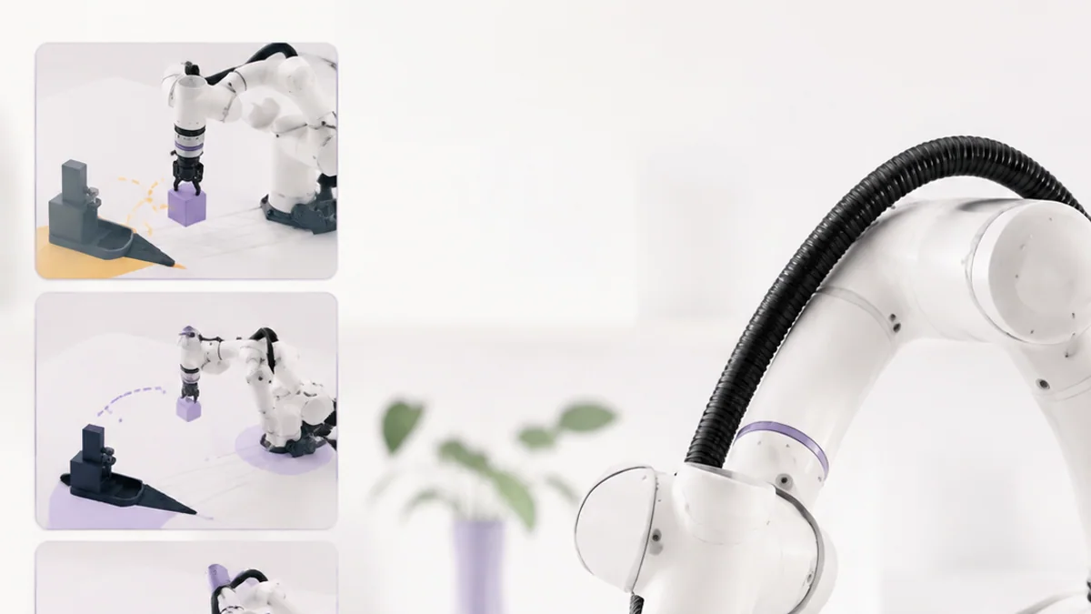
Offline programming builds and tests a robot sequence away from production. RoboDK uses a post processor to translate generic simulated instructions into the selected controller’s program format. Before production, engineers review generated code, confirm frames and tools, transfer through an approved method, then validate at reduced speed under the robot maker’s safety procedure.
Think of it like this: A translator can convert a carefully written route into another language, but a qualified driver still checks the real road before carrying passengers.
A concrete example
Simulate a pick-and-place cycle, check targets and collisions, select the correct robot post processor, generate the program, then perform supervised low-speed validation in the real cell.
The flow: Validate station → Choose post processor → Generate program → Reduced-speed proof
Try it yourself
- Write a pick-and-place program sequence.
- Create a pre-export checklist for robot, tool, frames and post processor.
- Add a reduced-speed real-cell validation plan with stop conditions.
Quick check — What does a post processor do?
It converts the generic offline program into syntax and structure for a specific robot controller.
Put the ideas together: Simulate a pick-and-place cell
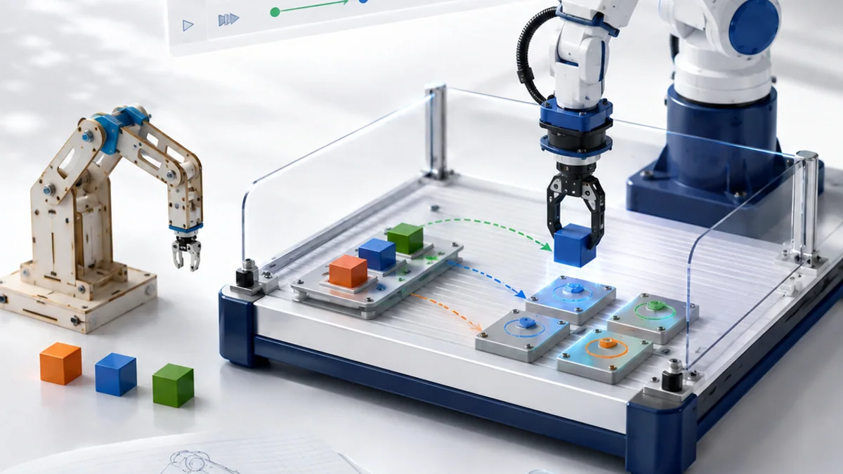
Design a RoboDK station that moves three parts from an input fixture to safe output locations with clear approaches and controller-ready logic.
Your build plan
- Create the station hierarchy, frames and tool centre point.
- Teach home, approach, pick, retreat and place targets.
- Choose motion types and inspect reach, configurations and collisions.
- Prepare generation and reduced-speed validation checklists.
Evidence to keep
- Station tree and frame diagram
- Target and motion sequence
- Collision and reach review
- Offline-programming validation checklist
An engineer does not stop at “it worked once.” Keep the diagram, record the conditions, repeat the test, and note what changed between attempts.
Important safety and quality notes
- Treat the simulation as a model, never as proof that a real cell is safe.
- Only trained and authorized people should operate or validate an industrial robot.
- Use guarding, approved stop systems and reduced-speed procedures required by the robot manufacturer and site.
- Confirm the active tool, frames, payload and program before any real motion.
The examples in this article are educational models. Check component ratings, manufacturer instructions, local rules and appropriate supervision before using real hardware.
Vocabulary without the jargon wall
| Term | Plain-language meaning |
|---|---|
| Station | A RoboDK project containing the robot, geometry, frames, targets and programs. |
| Reference frame | A coordinate system that locates an item relative to another item. |
| TCP | The tool centre point used as the working position and orientation of a robot tool. |
| Target | A stored robot pose or set of joint values. |
| Singularity | A robot configuration where some motions become poorly conditioned or require extreme joint speed. |
| Post processor | Software that generates controller-specific robot code from offline instructions. |
What to remember
RoboDK creates a digital robot station where frames, tools, targets and motion can be tested before controller-specific code is generated. The professional habit behind the technology is equally important: define the result, observe the system, measure what happened, and improve one thing at a time.
Continue with the full RoboDK learning path for the structured sessions, or explore the sources below when you are ready for deeper technical detail.
Sources and further learning
- RoboDK getting started — RoboDK
- Reference frames — RoboDK
- Create robot targets — RoboDK