
Intermediate to advanced · visual course

ROS

ROS connects independent robot programs through named interfaces so a complex system can be built, inspected and replaced one part at a time.

ROSLinuxPython 4 guided sessions 8 skill tracks 3 example projects
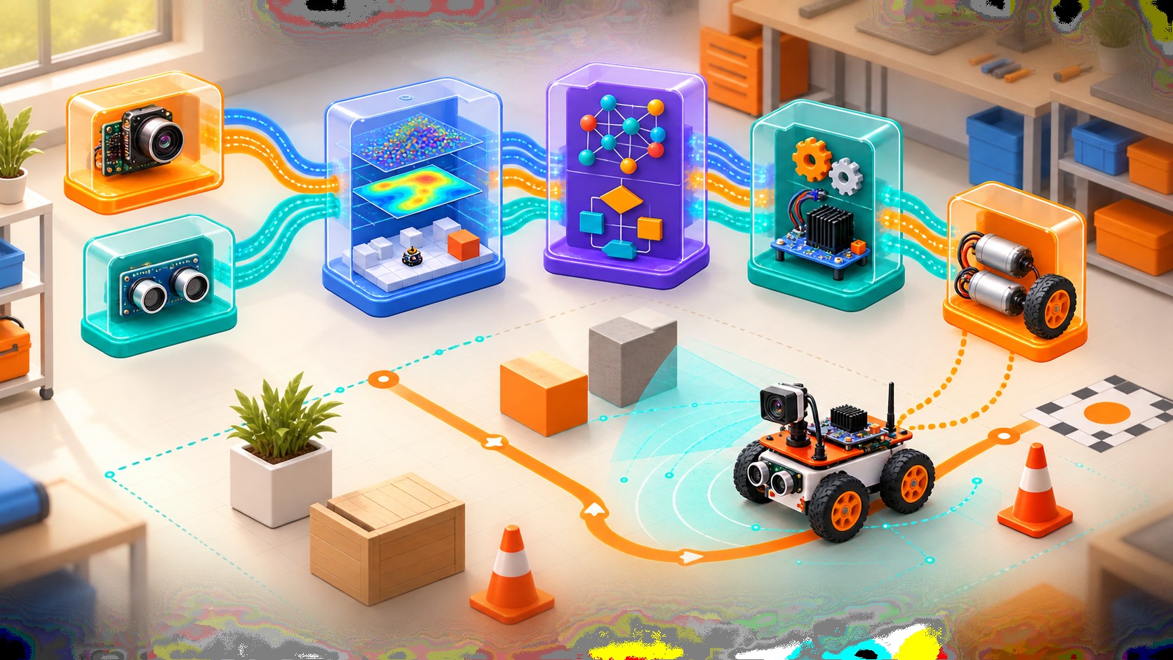
Three-dimensional robot software modules linked by sensor, mapping, decision and motor-control message paths
Concept overview · generated for this Academy4Tech lesson
Start here

See the system, then build it.

ROS is middleware and tooling, not the robot’s operating system in the everyday desktop sense.

01Read a ROS computational graph
02Choose topics, services or actions for a task
03Explain frames and timestamped sensor data
04Use simulation, logs and command-line tools to debug
Your progress Keep your learning momentum going

0 of 4 sessions complete

Interactive 3D learning studio

ROS graph studio

Inspect cooperating nodes, message paths, coordinate frames and the tools used to observe them.

Interactive system model · loads on request Poster mode
Explore the system in 3D Inspect the labelled subsystems and watch their modelled process. The lesson flow beside it is a separate conceptual sequence unless it explicitly names the same subsystem. The poster remains available if WebGL is unsupported.
Selected lesson · conceptual flow

Nodes and the robot graph

Why split robot software into separate nodes?

Step 1 of 4 · Sensor node

Step through this lesson’s conceptual sequence here. Inspect the separate 3D subsystem model below it to understand the system’s structure.

3D subsystem inspector · 4 model parts
Mini experiment

Change one variable. Predict first, then test.

Choose a useful publish rate from 10 to 25 Hz.

15 Hz
Live result Move the control to test your prediction

Choose a useful publish rate from 10 to 25 Hz.

Every highlighted 3D group corresponds to a labelled system part. A slider changes the model only when that relationship can be represented faithfully; otherwise the geometry stays still and the live calculation explains the effect. The model simplifies scale and geometry, so use the lesson’s safety notes, measurements and official documentation when building a real system.

01
Session 1 · 20 min

Nodes and the robot graph

Why split robot software into separate nodes?

Understand it

A node is a running participant with a focused responsibility, such as reading a camera or controlling wheels. Nodes form a graph through interfaces. Smaller responsibilities make components easier to test, reuse and replace.

Interactive concept flow

Step 1 of 4 Sensor node

Choose a step to inspect it, or run the complete sequence.

Sequence progress
1 / 4
Picture it

A useful analogy

A film crew has camera, sound, lighting and directing teams connected by clear communication.

Apply it

Worked example

A camera node publishes images, a detector node interprets them, and a motor node accepts safe velocity commands.

Try it
  1. Draw four nodes for a line-following robot.
  2. Name each responsibility.
  3. Add arrows showing information direction.
Quick checkShould one node usually do every robot task?

Answer: No. Focused nodes improve testing, reuse and fault isolation.

02
Session 2 · 25 min

Topics, services and actions

Which ROS interface fits each kind of communication?

Understand it

Topics carry ongoing one-way streams using publish and subscribe. Services handle short request-response work. Actions manage longer goals with feedback, a result and cancellation. Interface definitions keep message structure consistent.

Interactive concept flow

Step 1 of 4 Continuous stream

Choose a step to inspect it, or run the complete sequence.

Sequence progress
1 / 4
Picture it

A useful analogy

A radio broadcast is a topic, asking a desk for one fact is a service, and ordering a delivery with progress updates is an action.

Apply it

Worked example

Camera frames use a topic, resetting a map can use a service, and navigating to a goal uses an action.

Try it
  1. Classify six robot communications.
  2. Explain one ambiguous choice.
  3. Add the expected data fields for one message.
Quick checkWhy is navigation normally an action?

Answer: It takes time and benefits from progress feedback, a final result and cancellation.

03
Session 3 · 25 min

Time and coordinate frames

How do measurements from different sensors agree?

Understand it

Sensor data is measured at a time and in a coordinate frame. Transforms describe how frames relate, such as camera to robot base and robot base to map. Using the wrong frame or stale timestamp can place an object incorrectly.

Interactive concept flow

Step 1 of 4 Sensor frame

Choose a step to inspect it, or run the complete sequence.

Sequence progress
1 / 4
Picture it

A useful analogy

“Two metres ahead” is incomplete until we know ahead of what and at what moment.

Apply it

Worked example

Transform a point detected in the camera frame into the robot base frame before planning an arm movement.

Try it
  1. Draw map, robot and camera axes.
  2. Connect them as a tree.
  3. Describe what changes when the robot turns.
Quick checkWhat does a transform provide?

Answer: It describes the position and orientation relationship between coordinate frames.

04
Session 4 · 30 min

Simulate, observe and debug

How can we understand a distributed robot when something fails?

Understand it

Start with the graph: confirm expected nodes, interfaces and message rates. Inspect data, logs, parameters and transforms before changing code. Simulation allows repeatable tests without risking hardware, but physical validation is still required.

Interactive concept flow

Step 1 of 4 Observe graph

Choose a step to inspect it, or run the complete sequence.

Sequence progress
1 / 4
Picture it

A useful analogy

A doctor checks symptoms and measurements systematically before choosing a treatment.

Apply it

Worked example

If a robot does not move, check whether the command topic exists, messages arrive, safety node permits motion and motor controller reports faults.

Try it
  1. Create a fault tree for “robot does not stop”.
  2. List one observation at each system boundary.
  3. Choose a safe simulation test before hardware.
Quick checkWhy inspect interfaces before editing code?

Answer: The fault may be missing data, naming, timing or configuration rather than the algorithm itself.

Beyond the guided sessions

Explore the whole ROS field

The guided sessions teach the foundations. This map widens the view across 8 important tracks, with explanations, practice prompts, knowledge checks, and official sources for deeper study.

Build modular ROS 2 robot software, connect data and coordinate frames, then test complete systems for dependable and secure behavior.

Field map 0 of 8 tracks explored
Open a track to add it to your journey.
  1. Foundation Distributions, workspaces, and packages
    Track overview

    ROS 2 software is organized into versioned distributions, packages, and layered workspaces so a project can declare, build, and reuse its dependencies predictably. The examples here use the supported Kilted documentation; match them to the distribution installed on the robot.

    Core concepts

    Four ideas to understand

    1. ROS 2 distributions

      A distribution is a tested release set with a support window. Match tutorials and binary packages to the distribution installed on the robot instead of mixing releases.

    2. Workspace layers

      An underlay supplies existing packages, while an overlay contains project changes. Source them in order so package discovery resolves the intended version.

    3. Package manifests

      package.xml records a package's identity, maintainers, license, and dependencies. Accurate dependency declarations make builds reproducible on another machine.

    4. Build and source workflow

      colcon builds a workspace and places results in install space. Source the generated setup file in a new shell before asking ROS 2 to find the package.

    Check your thinking Why must an overlay be sourced after its underlay?
    Answer

    The later overlay takes precedence, so its packages and updated versions are the ones ROS 2 discovers.

  2. Foundation Nodes and the ROS graph
    Track overview

    A ROS 2 system is a runtime graph of small processes that discover one another and expose named interfaces, configuration, and diagnostics.

    Core concepts

    Four ideas to understand

    1. Focused nodes

      A node should own a clear responsibility, such as reading a lidar or estimating pose. Small responsibilities make components easier to test and replace.

    2. Names, namespaces, and remapping

      Names identify nodes and interfaces, namespaces separate repeated subsystems, and remapping reconnects them without changing source code.

    3. Parameters

      Parameters are node configuration values rather than high-rate data streams. Declare types, ranges, and defaults so invalid settings fail clearly.

    4. Graph introspection

      ROS 2 command-line tools can list nodes, interfaces, types, and connections at runtime. Inspect the graph before assuming that a publisher, subscriber, or name is correct.

    Check your thinking When is remapping better than editing a node's source?
    Answer

    Use remapping when only the runtime connection or namespace changes and the node behavior should stay reusable.

  3. Applied Topics, services, actions, and QoS
    Track overview

    ROS 2 offers different communication patterns; choosing by data lifetime, response needs, and network conditions prevents fragile robot behavior.

    Core concepts

    Four ideas to understand

    1. Topics

      Topics carry asynchronous streams from publishers to subscribers and suit sensor or state updates. Receivers do not send a direct reply to each message.

    2. Services

      A service is a brief request-and-response transaction, such as resetting a counter. It should not hold a client open for a long-running motion.

    3. Actions

      An action represents a longer goal and can return feedback, a final result, and accept cancellation. Navigation and manipulation tasks commonly need this lifecycle.

    4. Quality of service

      QoS policies control reliability, history, durability, and delivery timing. Publishers and subscribers need compatible policies, and best-effort can be sensible for disposable high-rate samples.

    Check your thinking Why is an action normally preferred over a service for driving to a distant pose?
    Answer

    The task is long-running and needs progress feedback, cancellation, and a final result, which actions provide.

  4. Applied Time, frames, and synchronized data
    Track overview

    Robots can combine observations only when every value has a meaningful timestamp and every pose is related through a valid coordinate-frame tree.

    Core concepts

    Four ideas to understand

    1. ROS clocks and timestamps

      A timestamp says when data was valid, not merely when a consumer received it. Simulation time must be used consistently so playback and simulated sensors agree.

    2. TF2 frame trees

      TF2 stores time-varying relationships in a tree where each frame has one parent. A connected, non-cyclic tree lets software ask for poses without hard-coded coordinate math.

    3. Static and dynamic transforms

      A fixed sensor mount uses a static transform, while moving joints or robot poses need timestamped dynamic transforms. Publishing the wrong kind can hide motion or waste bandwidth.

    4. Sensor synchronization

      Fusion should pair measurements from comparable times and account for transport delay. Approximate synchronization is useful only when its allowed time gap matches the motion and sensor rates.

    Check your thinking What is the practical difference between a static transform and a dynamic transform?
    Answer

    A static transform never changes after publication; a dynamic transform is updated over time for moving relationships.

  5. Applied Robot models, visualization, and simulation
    Track overview

    A consistent model links geometry, kinematics, sensors, and simulated physics so errors can be found before hardware is placed at risk.

    Core concepts

    Four ideas to understand

    1. URDF links and joints

      Links describe rigid bodies and joints constrain their relative motion. Joint axes, origins, limits, and parent-child relationships determine the kinematic model.

    2. Visual, collision, and inertial data

      Visual geometry is for appearance, collision geometry is usually simplified for computation, and inertial values affect physics. Treating them as interchangeable produces misleading simulation.

    3. RViz interpretation

      RViz displays models, frames, maps, paths, and sensor messages but does not simulate physical forces. It is a diagnostic view of published data.

    4. Physics simulation

      A simulator approximates contact, mass, friction, sensors, and actuators. Record assumptions and expect a reality gap rather than treating simulated success as hardware proof.

    Check your thinking Why can a visually correct URDF still behave badly in physics simulation?
    Answer

    Its collision shapes, mass, inertia, joint limits, or friction may be wrong even when the rendered geometry looks correct.

  6. Applied Perception, state estimation, and navigation
    Track overview

    Autonomous navigation turns calibrated sensor data into state estimates, environmental representations, planned paths, and closed-loop motion.

    Core concepts

    Four ideas to understand

    1. Sensor drivers and observation models

      A driver converts device data into standard messages with units, frames, covariance, and timestamps. Downstream algorithms need those semantics, not just numeric arrays.

    2. Odometry and state estimation

      Wheel, inertial, visual, or satellite estimates each have different drift and failure modes. Fusion combines complementary evidence but cannot repair bad calibration or timing.

    3. Mapping and localization

      SLAM builds a map while estimating pose; localization estimates pose in an existing map. Map scale, frame conventions, and sensor observability must be checked.

    4. Nav2 planning and control

      Nav2 separates global planning, local control, environmental costmaps, recovery behavior, and task orchestration. Its plugins and behavior trees let a system choose policies for a particular robot.

    Check your thinking What is the difference between SLAM and localization?
    Answer

    SLAM estimates a map and pose together; localization estimates pose against a map that already exists.

  7. Advanced Launch, lifecycle, and reusable architecture
    Track overview

    Production systems need controlled startup, configuration, health transitions, and reusable composition rather than a collection of manually launched terminals.

    Core concepts

    Four ideas to understand

    1. Launch descriptions

      A launch description starts coordinated nodes with arguments, namespaces, parameters, and conditions. Keep environment-specific values outside node logic.

    2. Managed lifecycles

      Lifecycle nodes separate unconfigured, inactive, active, and shutdown states. A supervisor can configure dependencies in order and avoid publishing before a component is ready.

    3. Composition and executors

      Components can share a process to reduce transfer overhead, while executors schedule callbacks. This improves efficiency but increases the need to understand callback blocking and fault isolation.

    4. Configuration contracts

      Versioned parameter files, interface definitions, and documented assumptions form a deployable contract. Validate required values at startup instead of silently accepting unsafe defaults.

    Check your thinking What does an inactive lifecycle state provide that an ordinary running node may not?
    Answer

    The node can hold configured resources without performing its active work, allowing orderly startup and safe transitions.

  8. Advanced Evidence, testing, security, and safe failure
    Track overview

    A dependable robot records evidence, tests components and integrations, limits network trust, and moves to a defined safe state when assumptions fail.

    Core concepts

    Four ideas to understand

    1. Rosbag evidence

      A bag captures selected messages for repeatable analysis and regression playback. Save configuration and software versions with it so the evidence remains interpretable.

    2. Automated and launch testing

      Unit tests check local logic, while integration and launch tests verify nodes, timing, and interfaces together. Include malformed data and unavailable dependencies, not only nominal cases.

    3. DDS security

      ROS 2 security can authenticate participants, encrypt traffic, and enforce access policies. Keys and governance files require controlled provisioning and rotation; encryption alone does not make application logic safe.

    4. Fault-safe behavior

      Watchdogs, timeouts, plausibility checks, and bounded commands detect stale or unsafe conditions. Each critical fault needs a deliberate response such as stop, hold, degrade, or request help.

    Check your thinking Why is encrypted ROS 2 traffic not enough to make a robot safe?
    Answer

    Encryption protects communication, but unsafe commands, software faults, bad credentials, or physical hazards still require validation and fail-safe controls.

Verified next steps

Official references

Use these primary sources to extend the explanations and check current guidance.

  1. Open Robotics ROS 2 Kilted Tutorials
  2. Open Robotics ROS 2 Kilted — Interfaces: topics, services, and actions
  3. Open Robotics ROS 2 Kilted — Quality of Service settings
  4. Open Robotics ROS 2 Kilted — Adding a frame (C++)
  5. Navigation2 Project Navigation Concepts (Rolling documentation; match to the installed release)
  6. Open Robotics ROS 2 Kilted — Understanding the security keystore
Three-project build pathway

Learn ROS by making it work.

Start small, combine the ideas, then complete a measured challenge. Every project includes a material list, four build milestones, evidence to collect, and a safe next step.

  1. Starter · 3–4 hours Build an observable ROS 2 sensor pipeline Learn one dependable building block Create a simulation-only publisher, validator, and dashboard that turn timestamped battery samples into a small ROS graph students can inspect, configure, and deliberately break.
    What you will learn

    Learning goals

    • Create and build a package in a sourced overlay workspace.
    • Choose topic names, message fields, parameters, and QoS for a sensor stream.
    • Use ROS 2 graph tools to distinguish discovery, naming, and data-quality faults.
    Prepare

    Materials and tools

    • A supported ROS 2 desktop installation and matching documentation
    • A code editor and two or more terminal windows
    • The standard ROS 2 command-line tools; no physical robot is required
    Build sequence

    Four milestones

    1. Write a one-page interface contract for a namespaced, timestamped simulated battery message and its valid range.

    2. Create a package with a configurable publisher and validator node, then build and source it from a clean shell.

    3. Launch both nodes, inspect the graph, and compare a compatible QoS pairing with one intentional incompatibility.

    4. Add stale-data and out-of-range warnings, then record a short run containing normal, invalid, and missing samples.

    Prove it works

    Evidence to collect

    • A graph capture shows the expected node, topic, namespace, type, and publisher/subscriber connection.
    • A results table demonstrates that valid, invalid, stale, and QoS-mismatched cases produce the predicted outcome.
    • A fresh-shell reproduction log shows the package builds, sources, launches, and stops cleanly without an undocumented step.
  2. Builder · 5–7 hours Map a rover with URDF and TF2 Connect multiple ideas into a working system Construct a small differential-drive rover model whose chassis, wheels, lidar, and camera form a coherent frame tree, then diagnose transform and timestamp failures in visualization.
    What you will learn

    Learning goals

    • Model links, joints, visual geometry, and sensor mounting transforms.
    • Separate fixed transforms from time-varying robot state.
    • Trace a measurement through frames and time instead of applying guessed coordinate offsets.
    Prepare

    Materials and tools

    • ROS 2 with robot-state publishing and visualization tools
    • A simple rover URDF or Xacro starter file and primitive meshes
    • A simulated joint-state and range-data publisher
    Build sequence

    Four milestones

    1. Sketch the intended frame tree and state the parent, child, units, and physical meaning of every transform.

    2. Build the rover description and verify joint axes, wheel placement, sensor orientation, and scale in visualization.

    3. Publish joint states and sensor data with consistent timestamps, then transform sample observations into the base frame.

    4. Inject a missing frame, reversed axis, delayed timestamp, and duplicate parent one at a time; document the symptom and correction.

    Prove it works

    Evidence to collect

    • The generated frame tree is connected and acyclic, and matches a dimensioned mounting sketch.
    • A known simulated target appears in the expected base-relative position for at least three rover poses.
    • A fault diary identifies each injected defect from observable evidence and records the minimal repair.
  3. Challenge · 8–12 hours Create a resilient navigation regression lab Test, measure, and improve a complete solution Build a repeatable simulated navigation mission that measures route completion, clearance, localization quality, recovery behavior, and safe failure across controlled faults.
    What you will learn

    Learning goals

    • Connect robot description, transforms, localization, planning, control, and lifecycle state into one testable system.
    • Define mission metrics and fault cases before tuning behavior.
    • Use launch files, logs, bags, and security boundaries to make results reproducible and reviewable.
    Prepare

    Materials and tools

    • ROS 2 and a compatible Nav2 simulator tutorial environment
    • A version-controlled workspace with launch, parameter, map, and test files
    • ROS 2 logging, bag recording, lifecycle, and graph-introspection tools
    Build sequence

    Four milestones

    1. Define a map, three mission poses, quantitative pass limits, software versions, and a clean baseline launch.

    2. Complete repeated baseline runs while recording completion time, path length, minimum simulated clearance, and recovery count.

    3. Inject blocked paths, stale localization, sensor dropout, and unavailable lifecycle nodes separately; configure bounded stop or recovery outcomes.

    4. Package an automated test report with configuration hashes, plots, bag excerpts, failure classification, and a release recommendation.

    Prove it works

    Evidence to collect

    • At least three baseline repetitions meet the declared metrics without unexplained configuration changes.
    • Every injected fault has an expected outcome and a timestamped trace proving recovery, refusal, or bounded stop.
    • Another learner can clone the project, select the documented ROS distribution, and reproduce the report from one launch workflow.
Words to know

Build your vocabulary.

Node
A running ROS participant with a focused role.
Topic
An asynchronous publish-and-subscribe data stream.
Service
A short request-response interaction.
Action
A longer goal with feedback, result and cancellation.
Frame
A named coordinate system.
Transform
The spatial relationship between two frames.
Work safely

Before you power or move anything.

  • Test motion logic in simulation first.
  • Keep a physical emergency stop and supervised test area.
  • Limit speed and acceleration during first hardware tests.
Keep studying

Official documentation.

These lessons simplify the first ideas. Use the original documentation when building, checking details or moving to the next level.

Continue learning

Related Academy4Tech content.

ProjectAdvanced

WildeBeest Pro

A complete dual-ROS autonomous-robot reference stack joining CAD, simulation, navigation, sensor fusion, a safety-oriented Arduino controller and an operator dashboard.

ROS 2 JazzyPythonC++Arduino

Learn by building.

Choose a real project, identify the smallest subsystem you can test, and document what the measurement tells you.