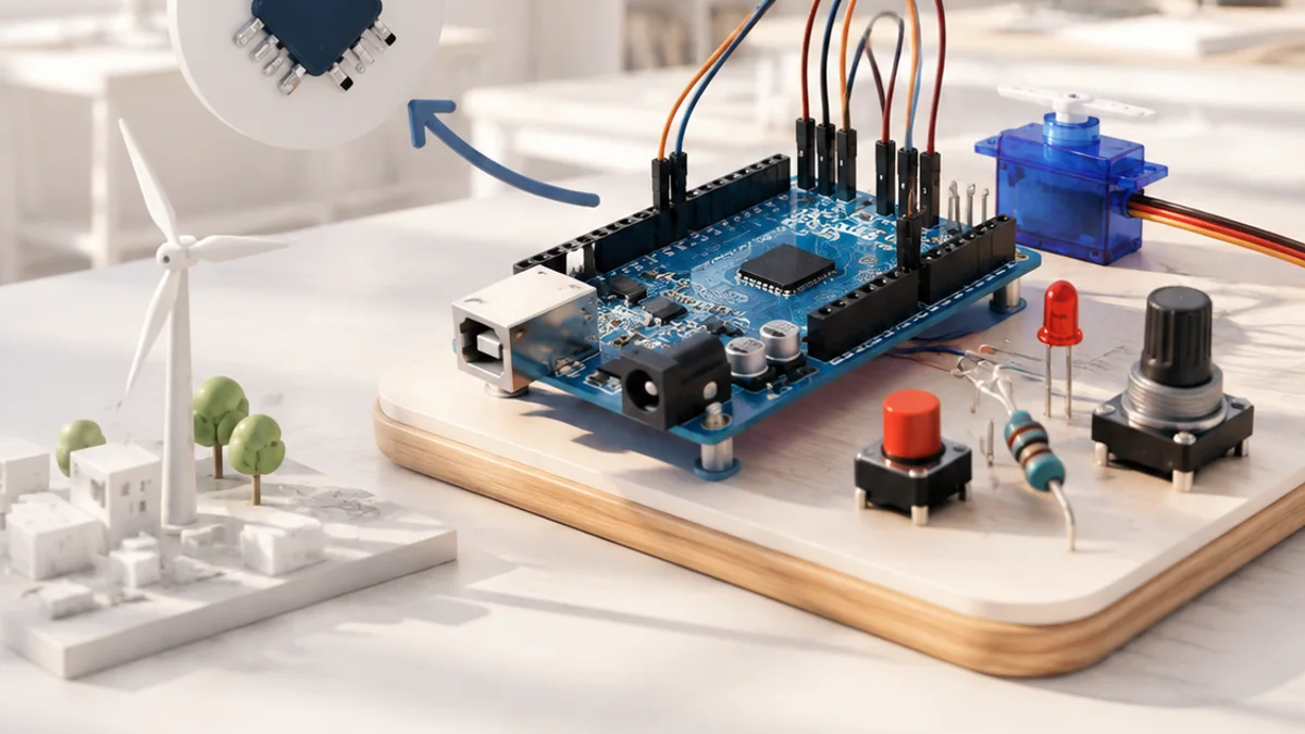
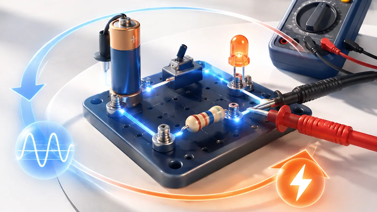
You can understand Electronics without treating it as magic or memorizing a long list of terms. Start with one simple mental model, connect each part to an everyday example, and then add the technical details that make the system dependable.
The big idea: Electronics controls energy and information through complete circuits whose voltage, current and resistance can be measured.
Start with batteries or current-limited bench supplies. Never experiment directly with wall electricity.
Why this matters
Electronics is the language spoken between power, sensors and controllers. Understanding a few core relationships makes wiring safer and turns random trial-and-error into measured troubleshooting.
By the end of this guide, you will be able to:
- Explain voltage, current and resistance in a closed circuit
- Calculate simple values with Ohm’s law
- Compare series and parallel connections
- Use a multimeter with correct mode and connection
The goal is not only to recognize the words. It is to explain the system, predict what it will do, and design a small test that produces evidence.
1. Voltage, current and resistance
The question: What moves through a circuit, and what controls it?
Voltage is potential difference between two points. Current is the rate of charge flow through a path. Resistance opposes current. For an ohmic component, V = I × R connects the three quantities.
Think of it like this: Water pressure resembles voltage, flow rate resembles current, and a narrow pipe resembles resistance—but the analogy has limits.
A concrete example
Across a 330 Ω resistor at 3.3 V, ideal current is 3.3 ÷ 330 = 0.010 A, or 10 mA.
The flow: Potential difference → Closed path → Resistance → Current
Try it yourself
- Cover one value in the Ohm’s-law triangle.
- Solve for current with 5 V and 1 kΩ.
- Check that units become milliamps.
Quick check — Can current flow through an open circuit?
Ideally no. The broken path prevents continuous charge flow.
2. Series and parallel
The question: How does connection shape change circuit behaviour?
Series components share one current path, and their voltage drops add. Parallel branches share the same two end nodes, so each branch has the same voltage. Adding a parallel branch lowers equivalent resistance and increases total source current.
Think of it like this: A single queue is series; several checkout lanes between the same entrance and exit are parallel.
A concrete example
Two 1 kΩ resistors in series total 2 kΩ; the same two in parallel equal 500 Ω.
The flow: Source → One path: series → Branches: parallel → Return
Try it yourself
- Draw two lamps in series and parallel.
- Mark equal current or equal voltage.
- Predict what happens if one lamp opens.
Quick check — What quantity is equal across ideal parallel branches?
The voltage across each branch is the same.
3. Components shape signals
The question: Why are different electronic components needed?
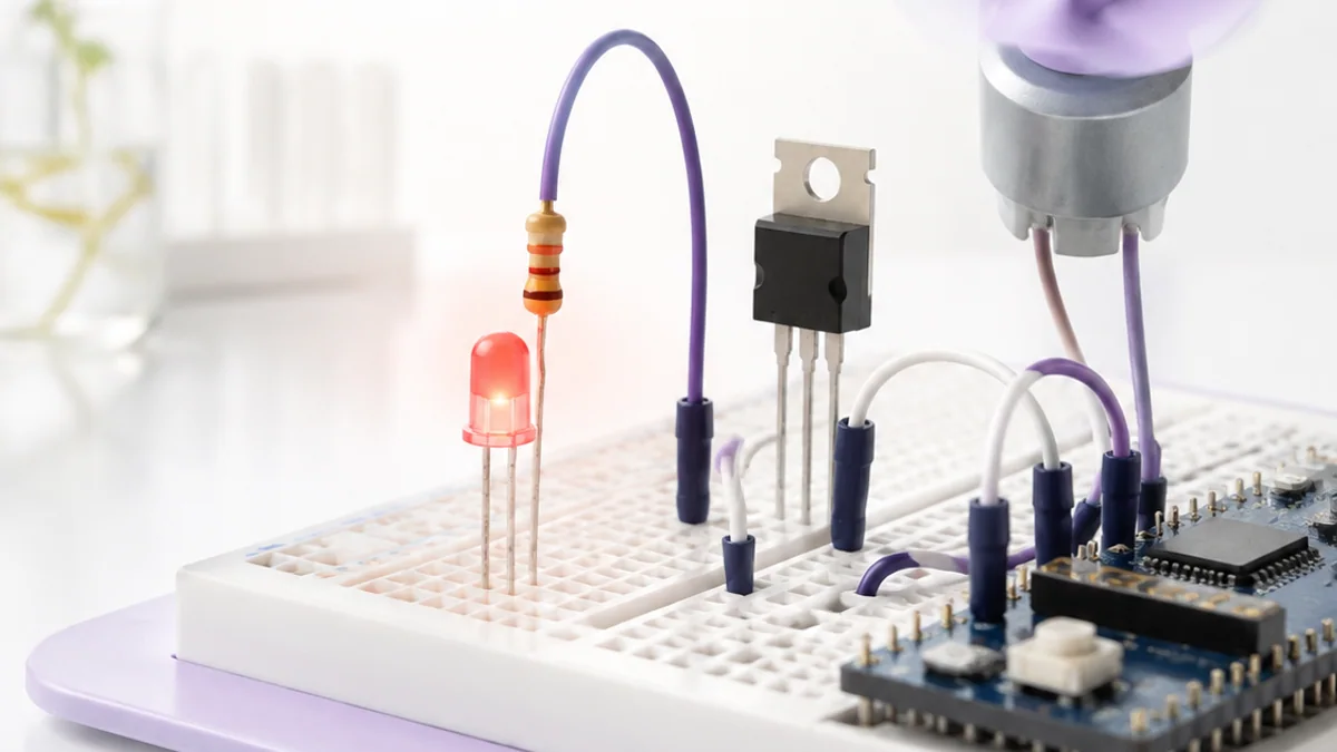
Resistors limit current and divide voltage. Capacitors store electric-field energy and smooth change. Diodes favour one current direction, while transistors use a small control signal to switch or regulate a larger path. Sensors change an electrical property with the environment.
Think of it like this: A toolbox has different tools because gripping, cutting and measuring are different jobs.
A concrete example
A resistor protects an LED, while a transistor allows a microcontroller to control a load requiring more current.
The flow: Signal or power → Component property → Changed behaviour → Useful output
Try it yourself
- Match five components to jobs.
- Choose a component for motor switching.
- Explain why a resistor alone is not a motor driver.
Quick check — What does a capacitor store?
Energy in an electric field, associated with separated charge.
4. Measure and troubleshoot safely
The question: How does a multimeter become part of the circuit?
Voltage is measured across two points with the meter in parallel. Current is measured by opening the path and inserting the meter in series. Resistance is measured only on an unpowered circuit. Begin with the correct port and range.
Think of it like this: A pressure gauge connects across a pipe section, while a flow meter must become part of the flow path.
A concrete example
To check an LED resistor, disconnect power, isolate the component if needed, select resistance and measure across it.
The flow: Choose quantity → Select port and mode → Connect correctly → Check reading
Try it yourself
- Draw meter connections for voltage and current.
- Circle the dangerous mistake of placing a current-mode meter across a battery.
- Write a three-step pre-measurement check.
Quick check — Why is current mode dangerous across a source?
The meter presents a very low-resistance path that can cause a large current, damage or injury.
Put the ideas together: Engineer an LED indicator
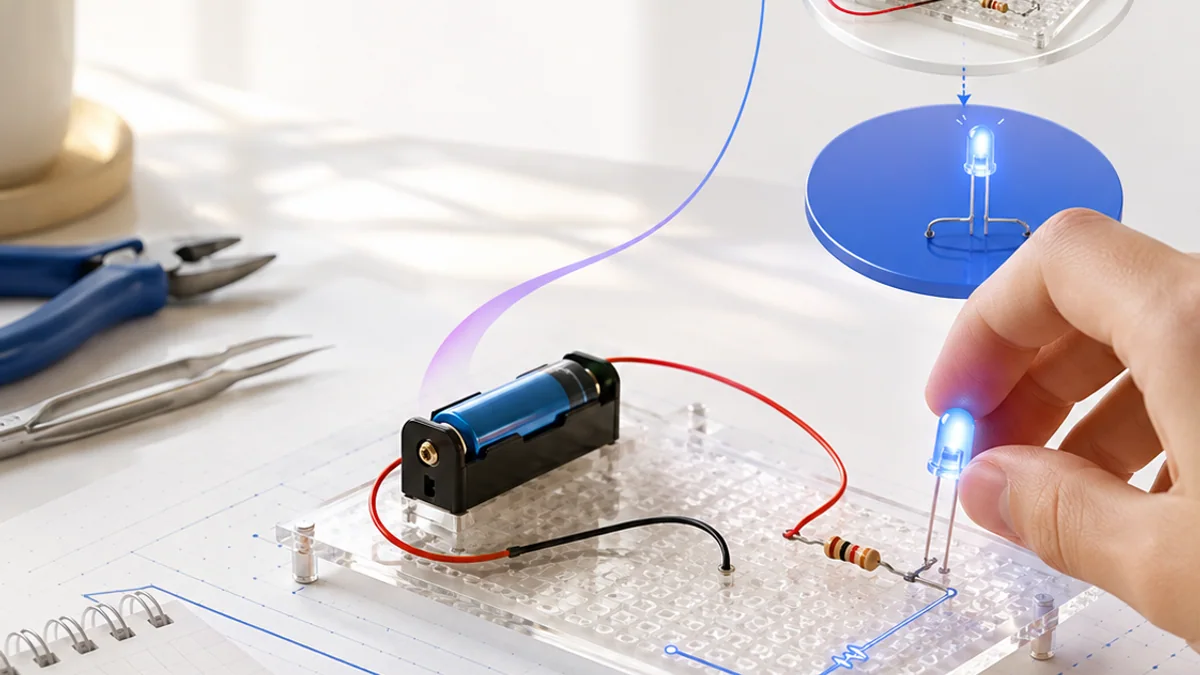
Design and verify a safe low-voltage LED circuit for a chosen battery or logic supply.
Your build plan
- Choose source and LED voltage.
- Calculate a suitable series resistor and power.
- Draw the circuit and meter test points.
- Predict and record voltage and current.
Evidence to keep
- Ohm’s-law calculation
- Circuit diagram
- Measurement plan
- Expected-versus-measured table
An engineer does not stop at “it worked once.” Keep the diagram, record the conditions, repeat the test, and note what changed between attempts.
Important safety and quality notes
- Use batteries or a current-limited low-voltage supply.
- Power off before moving wires or measuring resistance.
- Never place a meter in current mode directly across a source.
- Ask a qualified adult before working near mains-powered equipment.
The examples in this article are educational models. Check component ratings, manufacturer instructions, local rules and appropriate supervision before using real hardware.
Vocabulary without the jargon wall
| Term | Plain-language meaning |
|---|---|
| Voltage | Electric potential difference between two points, measured in volts. |
| Current | Rate of electric charge flow, measured in amperes. |
| Resistance | Opposition to current, measured in ohms. |
| Series | Components sharing one current path. |
| Parallel | Branches connected across the same two nodes. |
| Continuity | The presence of a complete conductive path. |
What to remember
Electronics controls energy and information through complete circuits whose voltage, current and resistance can be measured. The professional habit behind the technology is equally important: define the result, observe the system, measure what happened, and improve one thing at a time.
Continue with the full Electronics learning path for the structured sessions, or explore the sources below when you are ready for deeper technical detail.
Sources and further learning
- Arduino electronics learning resources — Arduino
- Ohm’s law: voltage, current and resistance — All About Circuits
- Direct-current electronics textbook — All About Circuits
Explore voltage, resistance and current
Ohm’s law links three quantities: current equals voltage divided by resistance.
Move a slider to explore the model.
Remember: this is a simplified learning model, not a hardware design or safety calculator. Real systems also include limits, noise, timing and failure handling.