You can understand Unmanned Ground Vehicles without treating it as magic or memorizing a long list of terms. Start with one simple mental model, connect each part to an everyday example, and then add the technical details that make the system dependable.
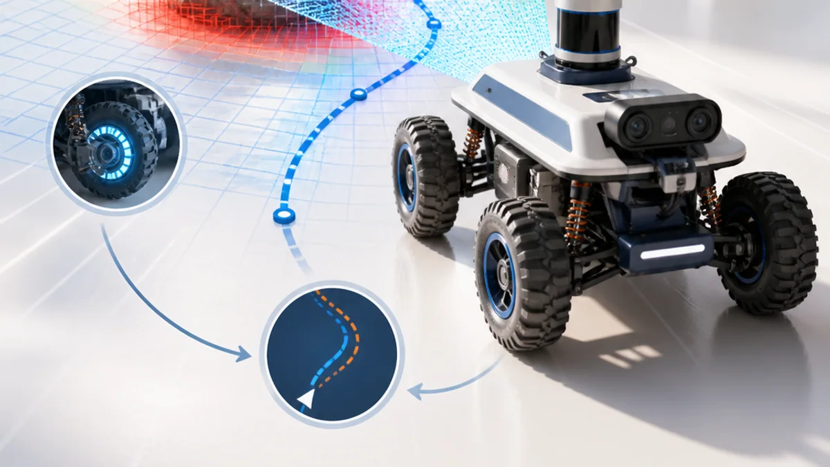
The big idea: A ground robot reaches a goal by turning wheel motion and sensor readings into an estimated position, a safe path and continuous steering corrections.
A route that works on a clean floor may fail on dust, grass or a ramp. Mobile robotics is the science of measuring and managing that uncertainty.
Why this matters
A ground robot must do more than drive its wheels. It needs to estimate where it is, decide where it can safely go and correct the route when wheels slip or the environment changes.
By the end of this guide, you will be able to:
- Compare differential and steering-based mobile robot motion
- Explain why wheel odometry drifts and how localization corrects it
- Trace a navigation loop through mapping, planning and control
- Design terrain and recovery tests with measurable results
The goal is not only to recognize the words. It is to explain the system, predict what it will do, and design a small test that produces evidence.
1. Chassis, traction and steering
The question: How do wheel speeds decide where a robot goes?
A differential-drive robot controls a left and right driven wheel independently. Equal speeds produce a straight path, different speeds produce a curve, and opposite speeds can rotate the chassis near its centre. Wheel diameter, track width, mass distribution, tyre grip and caster placement all affect the real motion.
Think of it like this: A person paddling a canoe turns by changing the effort on the two sides.
A concrete example
If the right wheel travels farther than the left wheel during the same time, the rover curves left. On loose sand, slip makes the real curve different from the calculation.
The flow: Wheel commands → Tyre forces → Chassis motion → Terrain response
Try it yourself
- Use two coins as left and right wheels.
- Move them equal distances, then move one farther.
- Sketch the expected path and one reason the real path could differ.
Quick check — What happens when ideal differential-drive wheels rotate at equal speed in opposite directions?
The robot rotates approximately in place around a point between the wheels.
2. Odometry and localization
The question: How does a rover know where it is?
Wheel encoders estimate how far each wheel turns. Odometry adds those small motions to update position and heading, but every slip or size error accumulates. Localization compares odometry with other evidence such as an IMU, lidar map, camera landmarks or GNSS. The result is a pose estimate with uncertainty, not perfect truth.
Think of it like this: Walking with your eyes closed, you can count steps, but small errors grow until a landmark helps you correct your position.
A concrete example
A wheel encoder predicts the rover moved 2 m, while a lidar scan best matches the map at 1.86 m. The localization system combines evidence rather than blindly trusting one source.
The flow: Encoder motion → Odometry update → Landmark comparison → Corrected pose
Try it yourself
- Mark a start pose on squared paper.
- Apply three forward and turn commands.
- Add a small error to each move and compare final predicted and true positions.
Quick check — Why does wheel odometry usually drift over a long route?
Small errors from slip, wheel size and measurement accumulate each time motion is added.
3. Map, plan and control
The question: How does a robot choose and follow a safe path?
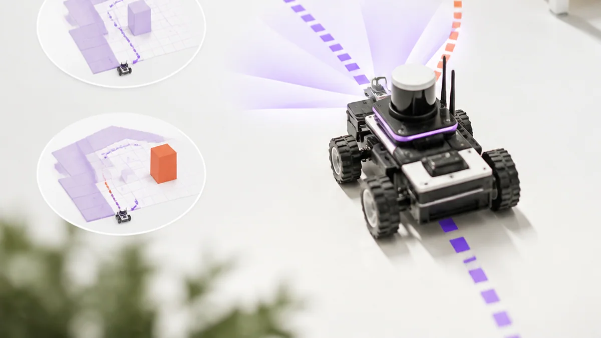
Sensors update an environmental representation such as an occupancy grid or costmap. A planner searches for a path from the estimated pose to the goal. A controller converts a nearby part of that path into velocity commands while reacting to local obstacles. Navigation software coordinates planning, control and recovery as a repeating loop.
Think of it like this: A route planner suggests streets, while the driver still steers around a temporary cone and checks where the car actually is.
A concrete example
A global path goes around a shelf. When a box appears, the local controller slows and steers around it, or stops and requests a new plan if no safe gap remains.
The flow: Sense obstacles → Update costmap → Plan path → Control wheels
Try it yourself
- Shade blocked cells on a paper grid.
- Draw a short safe path with clearance.
- Add a new obstacle and decide whether to steer locally, replan or stop.
Quick check — What is the difference between a planner and a controller?
The planner chooses a route toward the goal; the controller produces immediate motion commands to follow it safely.
4. Terrain, recovery and evidence
The question: What makes a rover reliable outside a perfect laboratory?
Real terrain changes traction, clearance, vibration and sensor visibility. Engineers define operating limits, test surfaces and slopes one at a time, then record pose error, completion time, current and recovery events. Recovery behaviour might stop, reverse, rotate for a better view, replan or ask a human for help.
Think of it like this: Hiking shoes, route choice and pace all change when a smooth pavement becomes a rocky hill.
A concrete example
A delivery rover must cross tile and carpet, climb a 7° ramp and stop 25 cm before an unexpected obstacle in at least 9 of 10 trials.
The flow: Define terrain → Run trial → Detect failure → Recover and measure
Try it yourself
- Choose three test surfaces and one slope.
- Write a pass condition for obstacle stopping and route completion.
- Create a recovery decision for wheel slip and a blocked path.
Quick check — Why should terrain tests change one condition at a time?
It makes the cause of a success or failure easier to identify and compare.
Put the ideas together: Design a campus delivery rover
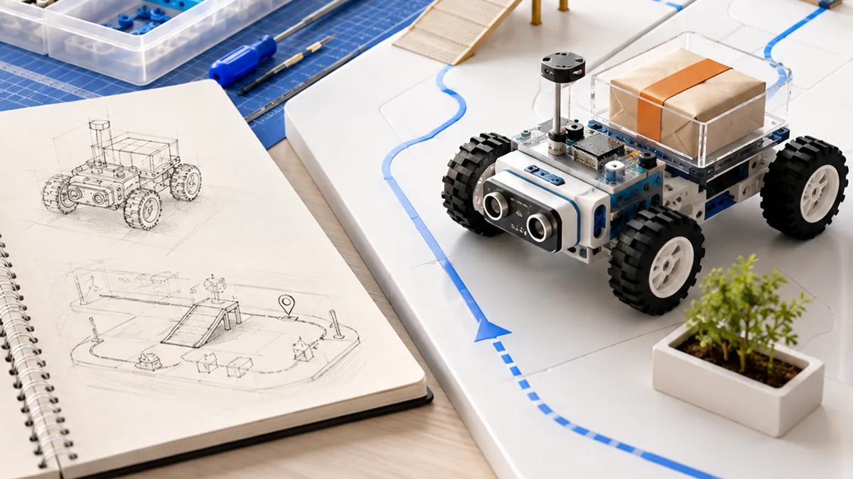
Plan a small autonomous ground vehicle that carries a light package through a mapped route with one ramp and changing obstacles.
Your build plan
- Choose the chassis, sensors, controller and power system.
- Draw the localization and navigation data flow.
- Map a route with clearance, a ramp and a blocked-path alternative.
- Define terrain, obstacle and recovery tests.
Evidence to keep
- Labelled rover system diagram
- Map and navigation flow
- Pose-error and terrain test table
- Recovery state diagram
An engineer does not stop at “it worked once.” Keep the diagram, record the conditions, repeat the test, and note what changed between attempts.
Important safety and quality notes
- Test at low speed in a bounded area with a reachable emergency stop.
- Keep hands, hair and loose clothing away from wheels and drive parts.
- Use a suitable motor driver, fuse or current limit and secured battery.
- Do not test autonomous vehicles near roads, stairs or members of the public.
The examples in this article are educational models. Check component ratings, manufacturer instructions, local rules and appropriate supervision before using real hardware.
Vocabulary without the jargon wall
| Term | Plain-language meaning |
|---|---|
| Differential drive | Steering produced by controlling left and right wheel speeds independently. |
| Encoder | A sensor that measures rotation or incremental movement. |
| Odometry | An estimate of motion calculated from movement measurements over time. |
| Pose | A robot’s estimated position and orientation. |
| Costmap | A grid representation that assigns travel cost to free, risky and occupied space. |
| Recovery | A behaviour used when normal navigation cannot continue. |
What to remember
A ground robot reaches a goal by turning wheel motion and sensor readings into an estimated position, a safe path and continuous steering corrections. The professional habit behind the technology is equally important: define the result, observe the system, measure what happened, and improve one thing at a time.
Continue with the full Unmanned Ground Vehicles learning path for the structured sessions, or explore the sources below when you are ready for deeper technical detail.
Sources and further learning
- Navigation concepts — Open Navigation / Nav2
- ROS navigation messages — Open Robotics
- Gazebo getting started — Open Robotics
Steer a two-wheel robot
Change the left and right wheel speeds. The difference between them determines how the robot turns.
Move a slider to explore the model.
Remember: this is a simplified learning model, not a hardware design or safety calculator. Real systems also include limits, noise, timing and failure handling.